9.9 Welding Joints in the Flat Welding Position
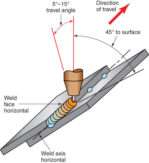
The face of a weld made in the flat welding position should be horizontal or nearly horizontal. The weld axis is also horizontal. See Figure 9-44. Any of the metal transfer methods may be used in the flat welding position. The method used depends on the metal thickness and other factors. Base metal positions and gun angles apply to both GMAW and FCAW.
9.9.1 Fillet Weld on a Lap Joint
The metal should be set up as shown in Figure 9-44. It should be tack welded about every 3″ (75mm). Tack welds hold the pieces in position while the weld is made.
To make the fillet weld, the centerline of the electrode should be held at about a 45° work angle. The electrode and gun should be tilted between 5°–15° forward from a true vertical position. This is a 5°–15° drag travel angle.
When the trigger on the gun is pulled, an arc forms, and a C-shaped weld pool is created. Point the electrode more toward the surface if the edge begins to melt too quickly. Adjust the position of the gun to maintain a C-shaped weld pool. Weld at a constant speed. Maintain the weld pool at the same size. With practice, gun angles and travel speed are mastered to produce a uniform width bead with uniform ripples in the weld face. See Figure 9-45.
Backtrack over the completed weld for about 1/4″ (6mm) when the end of the joint is reached. This movement helps reduce the crater that occurs if the weld is stopped at the end of the joint. No matter what type of weld is made, this same finish movement can be made. A run-off tab can also be used to eliminate the crater at the end of a weld.
Backhand welding with a 5°–15° drag travel angle allows for good weld bead control and produces good penetration. When welding on thin base metal, backhand welding can burn through the base metal. Switch to forehand welding on thin metal.
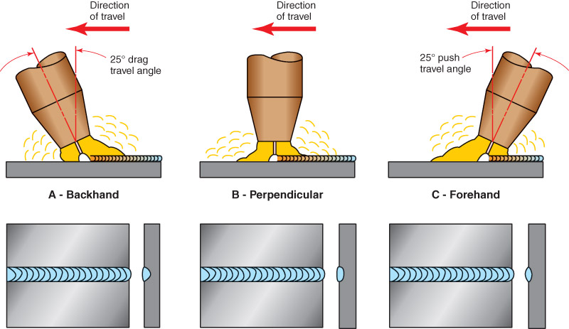
Figure 9-43 shows that the penetration in forehand welding is less than the penetration in backhand welding. A 5°–15° push travel angle is used. Forehand welding using a push travel angle provides the least penetration. Holding the gun perpendicular to the weld joint gives moderate penetration. Backhand welding using a drag travel angle provides the greatest penetration.
Changing from forehand to perpendicular to backhand increases penetration. This applies to all welding joints and positions.
9.9.1 Fillet Weld on a Lap Joint
The metal should be set up as shown in Figure 9-44. It should be tack welded about every 3″ (75mm). Tack welds hold the pieces in position while the weld is made.
To make the fillet weld, the centerline of the electrode should be held at about a 45° work angle. The electrode and gun should be tilted between 5°–15° forward from a true vertical position. This is a 5°–15° drag travel angle.
When the trigger on the gun is pulled, an arc forms, and a C-shaped weld pool is created. Point the electrode more toward the surface if the edge begins to melt too quickly. Adjust the position of the gun to maintain a C-shaped weld pool. Weld at a constant speed. Maintain the weld pool at the same size. With practice, gun angles and travel speed are mastered to produce a uniform width bead with uniform ripples in the weld face. See Figure 9-45.
Backtrack over the completed weld for about 1/4″ (6mm) when the end of the joint is reached. This movement helps reduce the crater that occurs if the weld is stopped at the end of the joint. No matter what type of weld is made, this same finish movement can be made. A run-off tab can also be used to eliminate the crater at the end of a weld.
Backhand welding with a 5°–15° drag travel angle allows for good weld bead control and produces good penetration. When welding on thin base metal, backhand welding can burn through the base metal. Switch to forehand welding on thin metal.
Figure 9-43 shows that the penetration in forehand welding is less than the penetration in backhand welding. A 5°–15° push travel angle is used. Forehand welding using a push travel angle provides the least penetration. Holding the gun perpendicular to the weld joint gives moderate penetration. Backhand welding using a drag travel angle provides the greatest penetration.
Changing from forehand to perpendicular to backhand increases penetration. This applies to all welding joints and positions.

Figure 9-44. A fillet weld on a lap joint in the flat welding position. Note the angles used and the deep penetration of the weld. Also, notice that the weld face and axis are horizontal or near-horizontal.
|
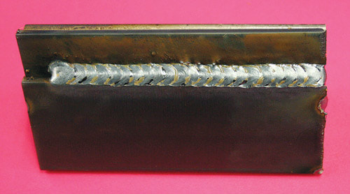
Figure 9-45. Lap joint with uniform weld bead width and ripple spacing.
|
9.9.2 Fillet Weld on an Inside Corner Joint
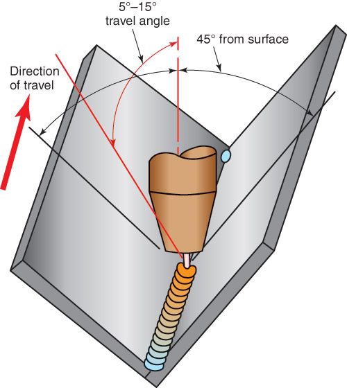
Fillet welds may be made on metal up to 3/8″ (10mm) thick without edge groove preparation. This can be done because of the deep penetration possible with the spray transfer method. The work angle should be held at a 45° angle to each metal surface. If the backhand welding method is used, the electrode and gun are held with a 5°–15° drag travel angle. See Figure 9-46. Figure 9-47 shows a fillet weld made using the travel angle described.
The GMAW process can generally be used to weld 1/4″ (6mm) beads on each pass. If the weld must be more than 1/4″ (6mm) thick, two or more weld passes are required.

Figure 9-46. A fillet weld on an inside corner joint in the flat welding position. The electrode is 45° from each metal surface. It is also tipped 5°–15° forward in the direction of travel.
|
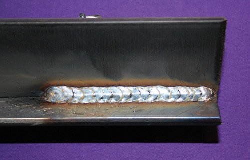
Figure 9-47. A completed fillet weld done in the flat position.
|
9.9.3 Groove Weld on a Butt Joint
Square-groove welds can be made on metal up to 3/8″ (10mm) thick without edge shaping. Butt welds of any thickness can be made using the GMAW process, as long as the edges of the metal are properly shaped. The groove angle on a V-groove butt weld can be narrower than the angle used with SMAW. Because of the penetration possible with spray transfer methods, the root face can be larger. The root face should not be increased if using short-circuiting transfer as the penetration is not as great as spray transfer. The root opening can be smaller with GMAW than the opening used for SMAW. Figure 9-48 shows a completed butt weld.
When a butt weld is being made, the centerline of the welding wire should be directly over the axis of the weld. A drag travel angle of between 5°–15° is correct for the backhand welding method. See Figure 9-49. Adjusting the travel angle to near zero reduced the penetration. A push travel angle, which is forehand welding, can be used to further reduce or control the penetration on thin metals.
A keyhole in the weld pool indicates that complete penetration is occurring. One problem that may occur in a groove weld made with GMAW is whiskers. Whiskers are lengths of welding wire that stick through the root side of a groove weld. Whiskers occur when the welding wire is advanced ahead of the weld pool.
The wire goes through the weld root and burns off. The burned-off length is left stuck in the weld. Whiskers can be prevented by slowing the welding speed. They can also be prevented by reducing the wire feed speed. A small weaving motion can be used to keep the wire from getting ahead of the weld pool.
9.9.4 Groove Weld on an Outside Corner Joint
An outside corner joint is set up as shown in Figure 9-50. A square- or prepared-groove weld may be used. The electrode angles are the same as those used for welds made on a butt joint. Since groove welds are made on the outside corner joint, whiskers can occur.
An outside corner joint is set up as shown in Figure 9-50. A square- or prepared-groove weld may be used. The electrode angles are the same as those used for welds made on a butt joint. Since groove welds are made on the outside corner joint, whiskers can occur.
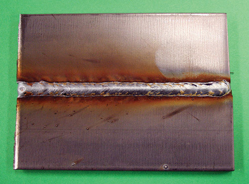
Figure 9-48. A completed butt weld.
|
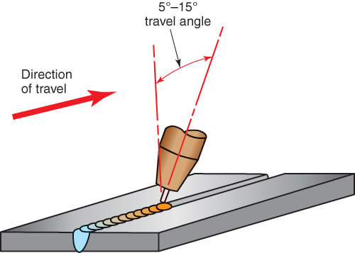
Figure 9-49. A V-groove weld on a butt joint in the flat welding position. Note the narrow (45°) groove possible with GMAW.
|
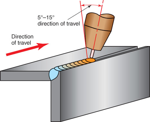
Figure 9-50. A bevel-groove weld on an outside corner joint in the flat welding position.
|
