|
9.5 Preparing Metal for Welding
To produce the highest quality welds, the base metal must be properly prepared. Preparation should be done just prior to welding. The weld joint will be clean and without oxidation. Many weld specifications do not require cleaning. This does not mean welding can be done on contaminated and oxidized surfaces. Contaminants and oxides can be trapped in the weld bead and produce a poor quality weld. Repair welding may be required on used, worn and oxidized metal. Even in these situations, the base metal should be cleaned as best as possible to prepare the metal for welding. Metal surfaces may be cleaned mechanically or chemically. Abrasive cloth or wire brushing may be used on lightly oxidized metals. Any abrasive from grinding should be wiped away prior to welding. Any chemicals used should be properly removed prior to welding. Highly oxidized or pitted or dirty base metals may need to be machined or ground to remove the affected material. If the metal being welded is expected to remain oxidized prior to welding, select a welding wire with more deoxidizers. Discuss the application with a welding wire supplier to obtain the best welding wire for the application. Joint designs for gas metal arc and flux cored arc welding are similar to those used for shielded metal arc welding. The groove angle used when GMAW or FCAW may be smaller than the angle used when SMAW. See Figure 9-41. This narrower angle is possible for two reasons. The wire diameters used are smaller and GMAW penetrates better than SMAW. A 45° groove angle takes less filler metal to fill than a 75° groove angle. Welding time is also less. Therefore, there are savings in filler metal and weld time. |

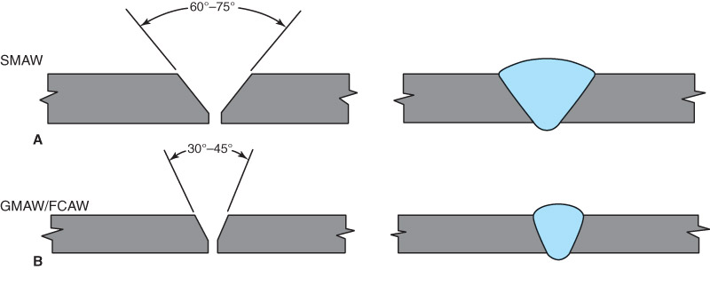
Figure 9-41. Arc welding beads compared. A—Typical groove angle and weld bead for SMAW. B—Typical groove angle and weld bead for GMAW and FCAW. Notice that less filler metal is required to fill the groove at B. Welding time is also less.
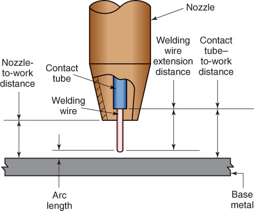
Figure 9-42
Figure 9-42. Electrode extension distance. Other distances important in GMAW and FCAW are also shown.
|
9.6 Electrode Extension
Electrode extension is the amount that the end of the welding wire sticks out beyond the end of the contact tube. See Figure 9-42. This distance is sometimes referred to as stickout.
A good extension for use with the short-circuit GMAW transfer method is about 1/4″ to 1/2″ (6mm to 13mm). The correct electrode extension for all other transfer methods varies between 1/2″ and 1″ (13mm and 25mm).
An electrode extension used for gas-shielded FCAW may vary from 1/2″ to 1 1/2″ (13mm to 38mm). The suggested electrode extension for use with self-shielding FCAW is 3/4″ to 3 3/4″ (19mm to 95mm).
A long extension may cause too much filler metal to be deposited with low heating by the arc. This may cause shallow penetration and a high-crowned weld bead shape. In spray transfer if the extension is too short, proper preheating of the welding wire does not occur. In FCAW-S, it is important to have the proper electrode extension. If the welding wire is not properly preheated, the flux will not properly produce the shielding gas necessary to protect the welding area.
