|
9.4 Setting Up the GMAW/FCAW Station
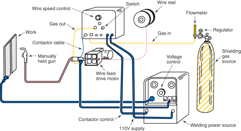
Figure 9-10 illustrates a complete GMAW outfit. The same equipment may be used for flux cored arc welding. Remember, self-shielding FCAW does not require any shielding gas. When setting up the GMAW or FCAW station, look for all potential safety problems. Spatter from GMAW or FCAW can cause a fire. All flammable materials must be removed from the welding area. 9.4.1 Setting Up a GMAW/FCAW Power Source In order to produce acceptable welds, a GMAW power supply must be properly adjusted for the material being joined and the desired metal transfer method. Before setting up the power source, the following information needs to be known:
First, adjust the voltage setting. The voltage determines the arc length and helps determine the metal transfer method. Other factors also affect the transfer method, as discussed in Headings 9.2.1 through 9.2.4. Second, adjust the wire feed speed. Welding machines with a wire feeder built in have the wire feed speed control on the machine itself. If the wire feeder is a separate unit, the wire feed speed adjustment is on the wire feeder. When the welder adjusts the wire feed speed, he or she is also adjusting the machine's nominal amperage. |

Figure 9-10. Diagram of a complete gas metal arc welding (GMAW) outfit.

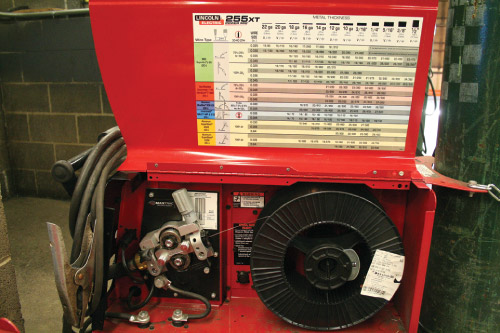
Figure 9-11. A welding wire reel on a wire feeder. (The Lincoln Electric Company)
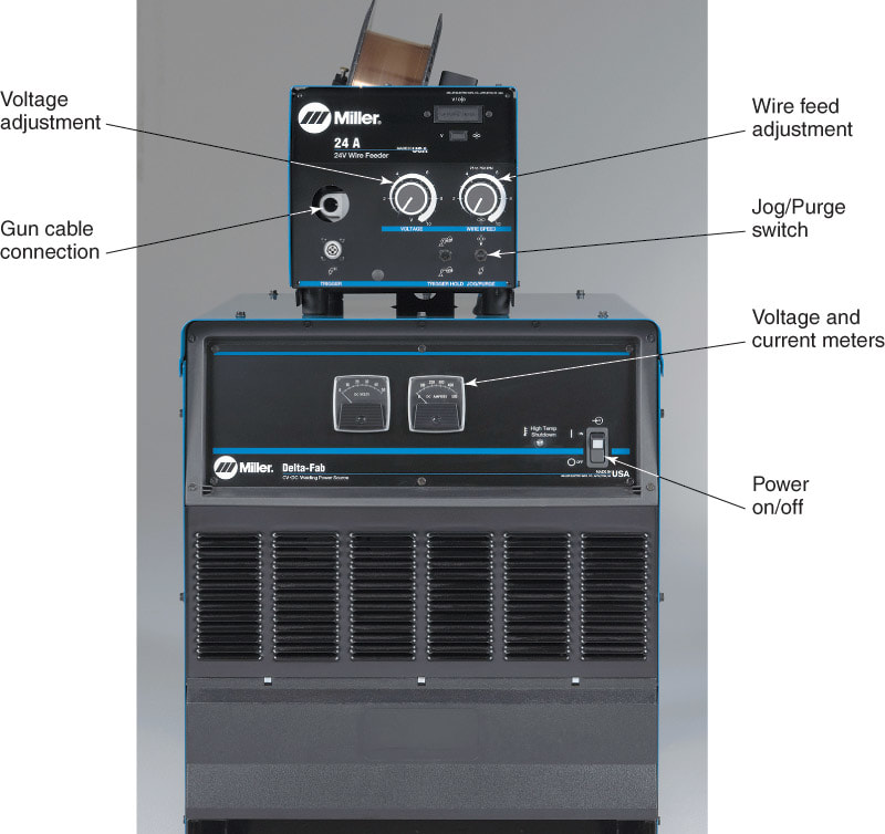
Figure 9-12. A GMAW/FCAW power source. (Miller Electric Mfg. Co.)
|
Procedure for Preparing a GMAW or FCAW Outfit
To prepare a GMAW or FCAW outfit for welding, the following steps should be taken:
To prepare a GMAW or FCAW outfit for welding, the following steps should be taken:
- Connect a separate wire feed unit to the welding power source, if required. The manufacturer's instructions should be followed to make these connections. Usually, a single cable assembly is enough to electrically connect the wire feeder to the welding machine. The welding lead from the positive terminal of the welding machine is usually connected to the wire feeder. Connecting the positive lead to the wire feeder provides DCEP current.
- Mount the desired welding wire reel (spool) onto the wire feeder. See Figure 9-11.
- Determine what shielding gas is required. See Heading 9.4.3. No shielding gas is required for self-shielded FCAW. Properly secure the cylinder (if used) to prevent it from being knocked over. Check that the regulator and gas flowmeter are attached properly. Connect a hose from the flowmeter to the welding machine or wire feeder as required. The GMAW and FCAW–G processes require a shielding gas connection. The FCAW–S process does not. Finally, the hose and fittings should be checked to make sure there are no leaks in them.
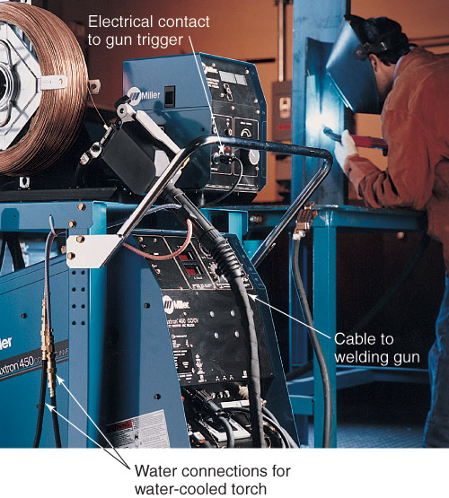
- Connect the welding gun to the correct place on the welding machine or wire feeder. Quite often, two connections need to be made. See Figure 9-9. One is the main cable that is connected where the welding wire exits the wire feeder. Attach this part of the cable assembly to its proper place. The second connection is for the electrical contact to the gun trigger. This part of the cable assembly also must be connected to its proper place. A water-cooled gun has additional connections.
- Connect the workpiece lead to the welding machine. Both the welding gun cable assembly and the workpiece lead should be checked for any signs of wear or cuts. Wear or cuts on the outside of these items may indicate damage to the leads.
- The workpiece clamp should be checked. The clamp should be clean so it can make a good electrical connection.
- If a water cooler is used, connect it to the welding machine or to the gun according to the manufacturers' recommendations. Usually, the welding machine, wire feeder, or welding gun is connected to the outlet on the water cooler. This way, cool water flows from the cooler to the gun. Warm water returning from the gun is connected to the inlet on the water cooler.
