|
9.2 Metal Transfer
Metal transfer occurs in using two methods. One is by the short-circuiting method. The second is to transfer metal across the arc. Methods of transferring metal across the arc include:
9.2.1 Short-Circuiting GMAW (GMAW–S) Short-circuiting gas metal arc welding (GMAW–S) is used with relatively low welding currents. Welding current, which is controlled by the wire feed speed, is lower for short-circuiting transfer than for globular or spray transfer. Globular and spray transfer are covered in the next two headings. Short-circuiting transfer is particularly useful on thin metal sections. Short-circuiting transfer is also useful to fill large root gaps or gaps between poor fitting parts. Short-circuiting transfer can be used in all positions. All position welds are made easily because there is no metal transfer across the arc. The weld pool cools and solidifies rapidly using the short-circuiting arc. Short-circuiting transfer results in low heat input into the base metal. Since short-circuiting gas metal arc welding has a low heat input, it is also used to weld thick sections in the overhead or vertical welding position. Refer to Figure 9-2 to see how the short-circuiting arc method deposits metal. The arc is terminated when the electrode touches the molten weld pool. Surface tension from the weld pool pulls the molten metal from the end of the electrode into the pool. A pinch forcearound the electrode squeezes the molten end of the electrode. The combined effects of surface tension and the pinch force separate the molten metal and the electrode. This separated portion of the electrode flows into the weld pool and flattens out. Once the molten metal from the electrode is separated from the electrode, the current jumps the gap between the new end of the electrode and the weld pool, reestablishing the arc. The continuously fed electrode again touches the molten pool and the process repeats. The process of shorting the electrode to the work repeats itself about 20 to 200 times per second. The pinch force, which acts to separate the end of the electrode, is created by current flowing through the electrode. Arc voltage, the slope of the power source, and the circuit resistance determine the strength of the pinch force. These factors—voltage, slope, and resistance—also affect the welding current. If a 150A current is set on the arc welding machine, the amperage may rise rapidly to the maximum output of the machine when the electrode short circuits; that could be 500A or more. An inductance circuit is built into the arc welding machine to control and slow down any rapid rises in current. Inductance is the property in an electric circuit that slows down the rate of the current change. Some arc welding machines have an electric coil built in near the welding current transformer coils. See Chapter 5 for a discussion of inductance. The current traveling through an inductance coil creates a magnetic field. This magnetic field creates a current in the welding circuit that is in opposition to the welding current. Increasing inductance in a welding machine slows down the increase of the welding current. Decreasing the inductance increases the rate of change of the welding current. Current rises too rapidly when too little inductance is used. The pinch force is so great that the molten metal at the end of the electrode literally explodes. A great deal of spatter occurs in this case. Current does not rise fast enough when too much inductance is used. The molten end on the electrode is not heated sufficiently. An ideal short-circuiting transfer rate and pinch force can be obtained by properly balancing the inductance and slope. Shielding gas also has an effect on short-circuiting transfer. Carbon dioxide (CO2) may be used as a shielding gas for short-circuiting transfer of carbon and lowalloy steels. CO2 produces greater penetration, but creates more spatter than an inert gas used for shielding. Mixtures of argon and CO2 are often used. They provide a good combination of improved penetration with minimal spatter. Stainless steel usually requires a mix of three gases. A typical mixture is 90% helium, 7 1/2% argon, and 2 1/2% CO2. Inert gases must be used on all nonferrous base metals. Nonferrous base metals are those that do not contain iron as the main element. This includes all metals except steels, steel alloys, and cast irons. Adding helium to argon increases the penetration. Argon and helium mixtures are used only on nonferrous base metals. See Figure 9-3 for the metal deposition rate for the short-circuiting transfer method. |

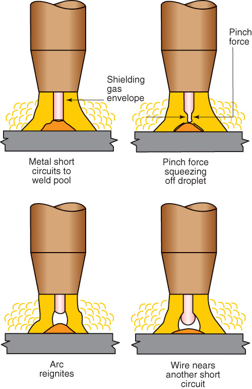
Figure 9-2. The sequence of metal transfer during the short-circuiting transfer method. A—The welding wire short-circuits to the weld pool. B—A magnetic pinch force squeezes off a droplet of molten electrode metal. C—The welding arc reignites. D—The electrode nears another short circuit condition and the process repeats itself.
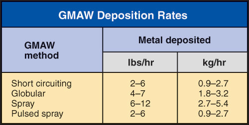
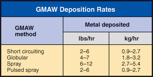
Figure 9-3. The approximate rate at which filler metal is deposited with various GMAW methods.
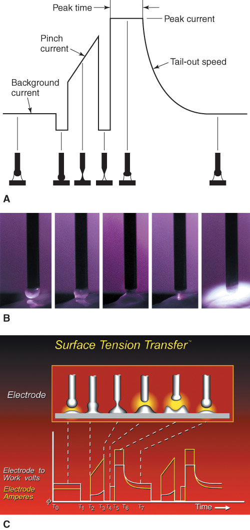
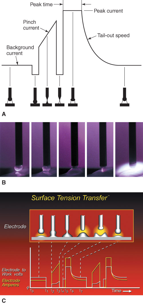
Figure 9-4. A—Changes in the welding current during a single STT® short circuit. B—High speed photos show what is happening at different stages of the STT® modified short-circuiting transfer process. C—An STT® diagram. (The Lincoln Electric Company)
|
Modified Short-Circuiting Transfer
Recent advancements in power supply technology have made modification of the short-circuiting transfer process possible. Power supplies alter or modify the current output of the power supply. An inverter power supply is used for modified short-circuiting transfer. The power supply uses feedback information to determine when to change the current from a low background current to a high peak current and to a near zero current. The result is a lower average current than regular short-circuiting transfer and less heat into the weld joint. Also the spatter from the process is significantly reduced.
Different power supply manufacturers have their own names for this modified process. The Lincoln Electric Company calls their process Surface Tension Transfer or STT®. Miller Electric Manufacturing Company calls their process Regulated Metal Deposition RMD™.
Figure 9-4 shows the current during a short-circuit cycle of the modified short-circuiting transfer process. At point A, the lower background current is flowing. The arc melts the end of the wire and the base metal. Just as the electrode shorts to the base metal at point B, the power supply reduces the current to near zero. There is no arc. After the short occurs, the current increases. At point C, the current is increasing to create the pinch force, which necks down the welding wire. A very important part of this process is that just as the molten end of the electrode is about to separate, the current is again reduced to a very low level at point D. The surface tension of the molten weld pool pulls the molten droplet off the end of the electrode and into the weld pool. There is no high current present when the molten droplet separates from the electrode. This low current prevents the end of the electrode from exploding or creating spatter.
After the droplet leaves the end of the electrode, the current increases to the peak current amount. The peak current is shown as point E in Figure 9-4. During this peak current period, the weld pool is very fluid. The high current helps the weld pool flow out to the toe of the weld. Finally, Point F shows a new droplet forming on the end of the electrode, the same as in point A. One complete short-circuit cycle is completed and a new one begins. This process is repeated 20 to 200 times per second.
This process introduces less heat into the base metal. Two current settings are used: a peak current and a background current. Peak current is necessary to establish the arc after a short circuit. Background current maintains the arc and is significantly less than the peak current. The average of these two currents is less than the current value set during the standard short-circuiting process covered earlier.
