9.12 Welding Joints in the Overhead Welding Position
The short-circuiting and pulsed spray metal transfer methods are recommended for overhead welding. For overhead welding, the welder should wear a cap, coat, cape, and possibly chaps. This is necessary to protect the welder from falling molten metal.
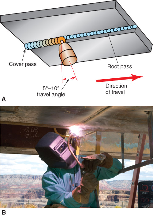
The angle of the electrode to the joint surfaces is the same as for other welding positions. The electrode should be held almost perpendicular to the weld axis for overhead welding. A travel angle of only 5°–10° is suggested. The weld pool in short-circuiting and pulsed arc transfer is relatively cool. A weaving motion is not required to cool the weld pool. As the weld pool increases in size, the possibility of the metal falling out or sagging increases. The use of several narrower beads, rather than a weaving motion, is recommended.
The angle of the electrode to the joint surfaces is the same as for other welding positions. The electrode should be held almost perpendicular to the weld axis for overhead welding. A travel angle of only 5°–10° is suggested. The weld pool in short-circuiting and pulsed arc transfer is relatively cool. A weaving motion is not required to cool the weld pool. As the weld pool increases in size, the possibility of the metal falling out or sagging increases. The use of several narrower beads, rather than a weaving motion, is recommended.
9.12.1 Fillet Welds
See Figures 9-59 and 9-60 for examples of the angles used to make fillets welds. The centerline of the electrode should be 45° from each metal surface. This is a 45° work angle. A drag or push travel angle is selected based on the metal thickness.
See Figures 9-59 and 9-60 for examples of the angles used to make fillets welds. The centerline of the electrode should be 45° from each metal surface. This is a 45° work angle. A drag or push travel angle is selected based on the metal thickness.
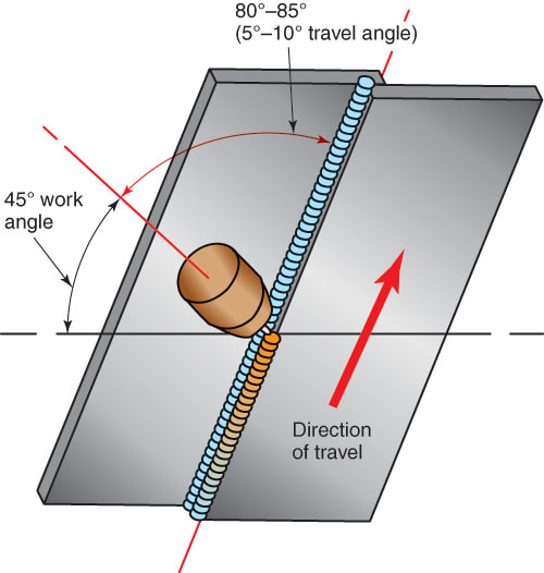
Figure 9-59. A fillet weld on a lap joint in the overhead welding position. In this joint, two passes are made. This is done to keep the weld pool size small and easy to manage.
|
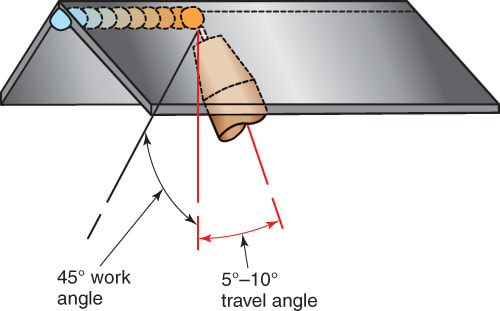
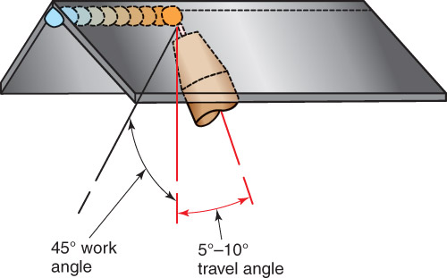
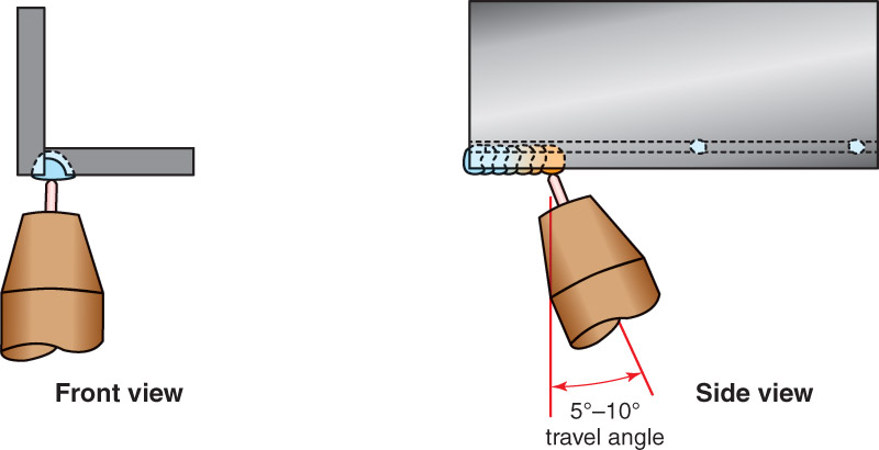
Figure 9-60. A fillet weld on an inside corner joint. The electrode and gun are tipped 5°–10° in the direction of travel.
|
9.12.2 Groove Welds
Figures 9-61 and 9-62 show the angles used to weld a butt joint and an outside corner joint in the overhead welding position.
Figures 9-61 and 9-62 show the angles used to weld a butt joint and an outside corner joint in the overhead welding position.

Figure 9-61. A—Bevel-groove weld on a butt joint in an overhead welding position being completed in two passes. B—A welder using FCAW to make a bevel-groove weld in the overhead welding position. (The Lincoln Electric Co.)
|

Figure 9-62. A J-groove weld in an outside corner joint in the overhead welding position.
|
9.13 Automatic GMAW and FCAW
Gas metal arc welding and flux cored arc welding can be semiautomatic or fully automatic processes. In the semiautomatic process, the welder must direct and move the arc welding gun while the welding wire feeds automatically into the weld pool.
Both GMAW and FCAW guns can be mounted on a motor-driven carriage or robot. Figure 9-63 shows a robot moving a GMAW gun. The process becomes fully automatic when the welding gun is controlled by a machine with feedback controls. Refer to Chapter 25 for information on robots and other automatic welding equipment.
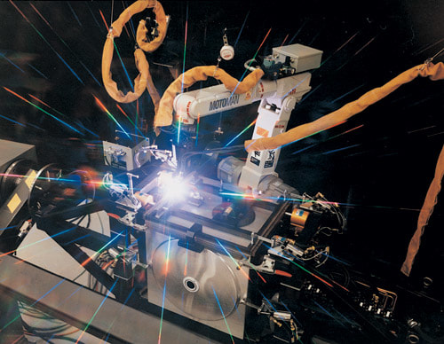
Figure 9-63. A GMAW gun mounted on a robot. The part is held in a fixture. (Motoman, Inc.)
