9.11 Welding Joints in the Vertical Welding Position
GMAW in the vertical welding position is performed using the short-circuiting or pulsed spray transfer method. Spray transfer can also be used, but only with small-diameter wire and a small molten weld pool. In the vertical welding position, the weld axis and the weld face are both vertical.
GMAW may be made uphill (from the bottom up) or downhill (from the top down). Downhill welding is more difficult with FCAW. The flux material might flow into the weld pool. This can be avoided if the welder can keep the weld pool ahead of the molten flux.
Backhand, perpendicular, and forehand welding can all be done on a vertical weld joint. As with other welding positions, backhand welding gives the best penetration and forehand the least.
The weld pool remains relatively cool when the short-circuiting method of metal transfer is used. A properly adjusted pulsed spray arc allows time between pulses for the weld pool to cool. Spray arc transfer can be used in some applications, but the weld pool must be kept small. To maintain a small weld pool, a higher travel speed must be used. The short-circuiting method of metal transfer keeps the weld pool coolest.
9.11.1 Fillet Weld on a Lap Joint
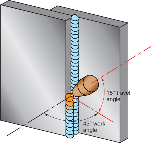
Figure 9-57 illustrates a multi-pass fillet weld being made in the vertical welding position. The angles of the electrode and gun are the same as for other positions. For best penetration, use a 5°–15° drag travel angle. A work angle of 45° should be used. If the edge of the metal melts too rapidly, adjust the work angle and point the electrode more toward the flat surface. Be certain that both the edge and surface are melting completely as the filler metal is added. The appearance of a C-shaped molten weld pool indicates good fusion.
Figure 9-57 illustrates a multi-pass fillet weld being made in the vertical welding position. The angles of the electrode and gun are the same as for other positions. For best penetration, use a 5°–15° drag travel angle. A work angle of 45° should be used. If the edge of the metal melts too rapidly, adjust the work angle and point the electrode more toward the flat surface. Be certain that both the edge and surface are melting completely as the filler metal is added. The appearance of a C-shaped molten weld pool indicates good fusion.

Figure 9-57. A fillet weld on a lap joint in the vertical welding position. Two passes are being used on the weld. Notice that the weld axis and bead face are vertical.
9.11.2 Fillet Weld on an Inside Corner Joint
The centerline of the electrode should be held at a 45° work angle. As with welding on other joints in other positions, a travel angle of 5°–15° is a good angle to use. A C-shaped weld pool indicates good fusion is occurring. Short-circuiting transfer and pulsed spray transfer are best suited for vertical welding. Spray arc can be used with a weaving motion in some applications.
The centerline of the electrode should be held at a 45° work angle. As with welding on other joints in other positions, a travel angle of 5°–15° is a good angle to use. A C-shaped weld pool indicates good fusion is occurring. Short-circuiting transfer and pulsed spray transfer are best suited for vertical welding. Spray arc can be used with a weaving motion in some applications.
9.11.3 Groove Weld on a Butt or Outside Corner Joint
A V-groove butt weld in progress is shown in Figure 9-58. The electrode centerline should be directly above the weld line. The electrode and torch should be inclined (tipped) 5°–15° in the direction of travel. This is a drag travel angle. On thin metals, a push travel angle is used. A keyhole at the root of the weld indicates complete penetration.
A V-groove butt weld in progress is shown in Figure 9-58. The electrode centerline should be directly above the weld line. The electrode and torch should be inclined (tipped) 5°–15° in the direction of travel. This is a drag travel angle. On thin metals, a push travel angle is used. A keyhole at the root of the weld indicates complete penetration.
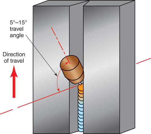
Figure 9-58. A V-groove weld on a butt joint. The root pass is in progress.
