9.10 Welding Joints in the Horizontal Welding Position
|
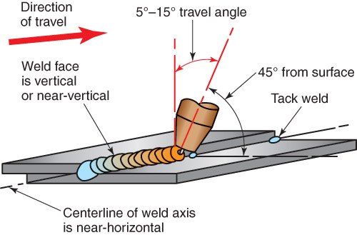
The face of a weld made in the horizontal welding position is vertical or nearly vertical. In the horizontal welding position, the centerline of the weld axis is horizontal or nearly horizontal. See Figure 9-51.
Short-circuiting, globular, spray, or pulsed spray transfer methods can be used for welding horizontal fillet welds. Horizontal butt welds are limited to short-circuiting and pulsed spray transfer. Trying to use the globular or spray transfer method results in a weld pool that is too large and fluid to manage. Also, metal transferred in globular form will not fall into the weld pool. 9.10.1 Fillet Weld on a Lap Joint For practice welds, the metal should be set up and tack welded as shown in Figure 9-51. The centerline of the electrode should be about 45° to the edge and metal surface. It may point more toward the surface if the edge melts too quickly. Use a backhand, forehand or perpendicular gun angle as necessary based on the metal thickness. Backhand method provides the best penetration. A drag travel angle of 5°–15° provides for good control and penetration. The typical C-shaped weld pool indicates that both the edge and surface are melting properly. |

Figure 9-51. A fillet weld on a lap joint in the horizontal welding position. In the horizontal welding position, the weld axis is near-horizontal and the face of the weld near-vertical.
|
9.10.2 Fillet Weld on an Inside Corner or T-Joint
Square or prepared-groove welds may be made in the horizontal welding position. The use of a V-, bevel-, U-, or J-type prepared groove depends on the metal thickness and joint design. The bead width used in GMAW does not have to be as wide for the same thickness as when doing SMAW. This is because the gas metal arc weld penetrates deeper. It does not need bead width and reinforcement to strengthen the weld.
The electrode should be held at a 45° work angle. Aiming the wire more toward the vertical surface may improve the bead shape. This helps compensate for the molten metal sag. For the best penetration and weld pool control, use a 5°–15° drag travel angle. On thin metals, use a 5°–15° push travel angle. See Figure 9-52 for gun angles. Figure 9-53 shows a completed weld.
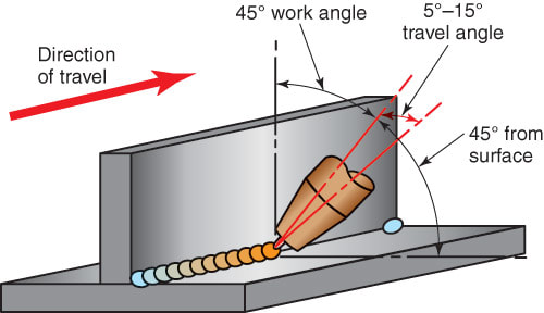
Figure 9-52. A fillet weld on a T-joint in the horizontal welding position. Note the angles from the metal and in the direction of travel.
|

Figure 9-53. A completed fillet weld.
|
9.10.3 Groove Weld on a Butt Joint or Outside Corner Joint
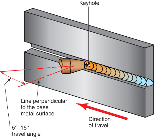
A square- or prepared-groove weld may be used. Figure 9-54 shows a U-groove weld in progress. The electrode centerline should be directly over the weld line. For best weld pool control, use a 5°–15° drag travel angle. The gun and electrode should also point upward slightly to keep the molten metal from sagging. Short-circuiting transfer and pulsed spray transfer allow the molten weld pool to cool slightly. Figure 9-55 shows a GMAW butt joint welded in the horizontal position.
To ensure complete penetration, watch for a continuous keyhole through the root pass. More than one pass is necessary on thicknesses above 3/16″ (5mm). To completely fill the groove, an electrode weaving motion may be required. Figure 9-56 shows a horizontal butt joint being welded.
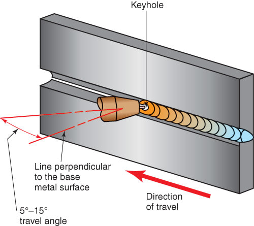
Figure 9-54. A U-groove weld on a butt joint in the horizontal welding position. Note the keyhole at the root of the weld.
|
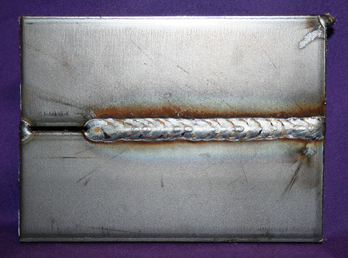
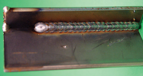
Figure 9-55. A GMAW butt joint welded in the horizontal position.
|

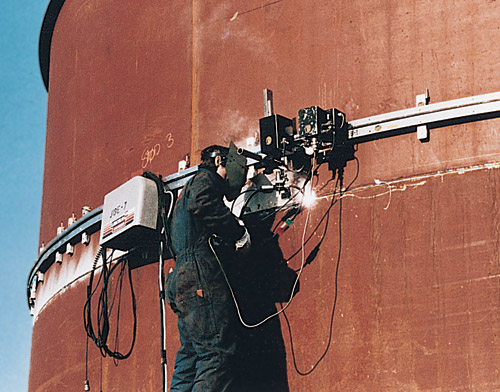
Figure 9-56. A mechanized GMAW machine mounted on a track. The track guides the GMAW gun along the circular butt joint on this large tank. (Bug-O Systems, Inc.)
|
