|
7.2 Arc Welding Power Sources for GTAW
Welding power sources for gas tungsten arc welding (GTAW) can be alternating current (ac), direct current (dc), or both alternating and direct current (ac/dc) in one machine. The most popular arc welding power source is the transformer-rectifier type. This machine produces both ac and dc current. Other arc welding power sources include the transformer and generator. Transformer-type machines produce only ac; generator-type machines produce ac, dc, or both types of current. Gas tungsten arc welding power sources must supply a constant current. In constant current machines, the volt-ampere curve is either drooping or a true constant current. A drooping volt-ampere curve has a steep slope. The amperage will change slightly as the voltage changes. This allows a welder to vary the amperage by changing the arc length. Newer power supply designs have nearly a vertical line on the voltampere curve. This is a true constant current power source, because the amperage is constant even though the voltage changes. This is made possible by using electronics to control the power supply. These electronically controlled power sources are more efficient, more responsive, and more repeatable. They also produce an excellent pulsed welding current. Figure 7-2 shows volt-ampere curves for drooping and constant current welding power sources. Two drooping curves are shown in this illustration. Curve 1 is for an 80V open circuit voltage set for a 150A maximum welding current. A 5V change in the closed circuit (welding) voltage from 20V to 25V, represents a 25% change in voltage with only an 8A, or 5%, change in the current. Curve 2 represents a curve for an 80V open circuit voltage set for 52A maximum welding current. A 25% change in voltage (from 20V to 25V) will only change the amperage about 2A, or 4%. The amperage is therefore considered to be relatively constant with large changes in voltage. Figure 7-2 also shows two curves (3 and 4), for an electronically controlled constant current power source. The same voltage change from 20V to 25V produces almost zero change in amperage. An ac or a dc welding machine can be the power source for GTAW. Most often, the machine will produce both ac and dc constant currents. Figures 7-3 and 7-4 show GTAW power sources. A direct current power source can be equipped with a device that produces a high-frequency voltage and feeds it into the welding circuit. In a dc circuit, high-frequency voltage is used only for starting the arc. Once the dc welding arc is stabilized, the superimposed high-frequency starting voltage is automatically stopped. High-frequency voltage is produced by an oscillator or a similar device. Several thousand volts are produced at a frequency of several million cycles per second or megahertz. The current in this high-frequency circuit is only a fraction of an ampere. Current and voltage reverse directions many times each second when ac welding. The electrode is positive, then the voltage switches so the electrode is negative. This repeats continuously when ac welding. An ac power source must have a way to keep the current flowing while the current switches from electrode-negative to electrode-positive. Without a method to keep the current flowing, there would be no arc during the electrode-positive part of the cycle. When the current is reduced or there is no current flowing during half the ac cycle, the arc is said to be partially or completely rectified. This is not good for the welding machine or the weld. To reduce or eliminate such rectification, the following methods are suggested:
Almost all GTAW machines currently produced use high-frequency or have a square-wave output. For a more complete understanding of welding power sources, review basic information about the construction, operation, and control of ac, dc and inverter power sources in Chapter 5. |
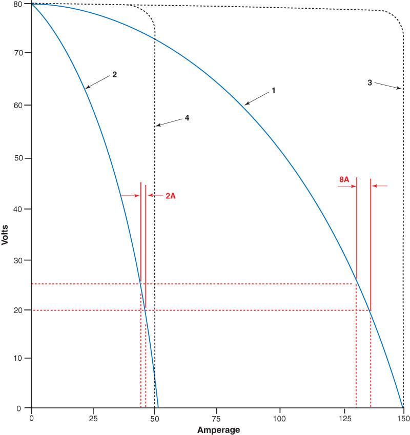
Figure 7-2. The volt-ampere curves for a drooper type and constant current power source. Curves 1 and 2 are drooper curves that show an 8A and a 2A change with a change of 5V. Curves 3 and 4 are true constant current curves. They show a nearly constant amperage with voltage changes.
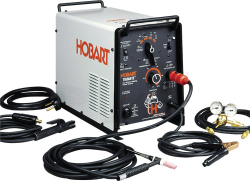
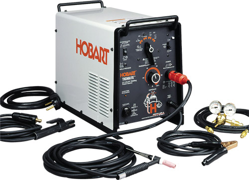
Figure 7-3. An ac/dc, single-phase power source for GTAW. (Hobart Brothers Co.)
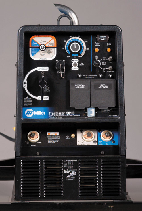
Figure 7-4. The face of a CC/CV and AC/DC welding power source. (Miller Electric Mfg. Co.)
|
