6.6 Starting, Stopping, and Adjusting the Arc Welding Power Source for SMAW
Before beginning to weld, inspect the complete arc welding station to make certain it is safe for use. See Heading 6.4. An arc welding machine should never be started or stopped under load (with the electrode or holder in contact with the workpiece or table). Make certain that the electrode holder is hung on an insulated hanger before turning the machine on or off. The electrode holder should never be left on the workbench.
Arc welding machines powered by ac are easy to start and stop. An on-off switch or buttons are provided on the machine. An engine-driven arc welding machine must have the engine started in order to start operating. Once the engine is running and up to its operating speed, the welding current may be turned on using an on-off switch.
Constant current-type arc welding machines are used for manual arc welding processes. The desired current is set on the machine. Amperage (current) controls vary in appearance, location, and operation on various manufacturers' machines. The voltage on a constant current machine is not set. It varies as the welding circuit resistance changes to maintain a constant or relatively constant current output. All electrical connections must be tight. The length of the arc gap will then control the welding circuit resistance, and therefore, the circuit voltage.
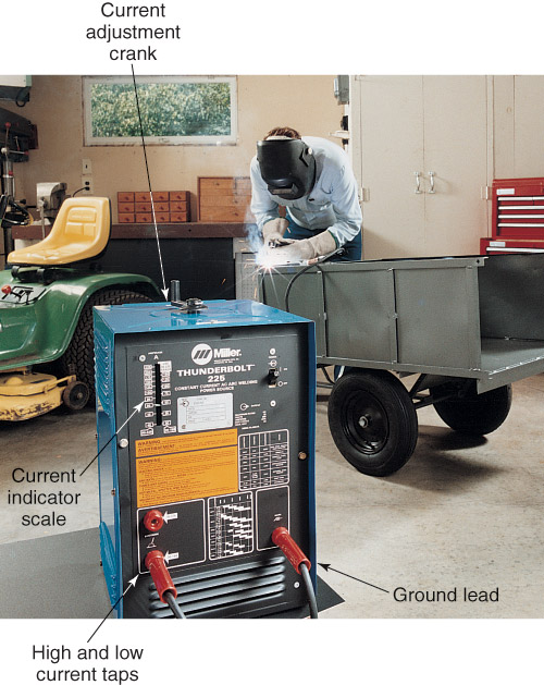
Figure 6-12 shows a machine that uses a tap-type control for coarse current adjustment and a crank on top of the machine for fine adjustment. As the hand crank is rotated, the primary coil is moved to vary the current output. A pointer moves with the primary coil, indicating the current setting on a scale on the outside of the cabinet.

|
|
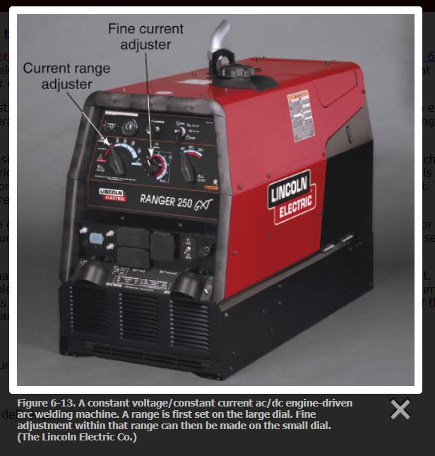
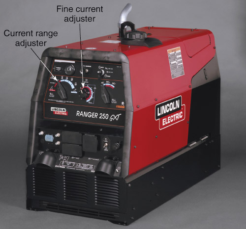
Figure 6-13 shows a shielded metal arc welding machine that uses a coarse current adjustment and a fine current adjustment. The fine current adjustment is made using a rotary knob. Fine adjustment controls are often marked with numbers from 0 to 10, or from 0 to 100. These numbers do not represent current, but rather percentages. Once a coarse current range is selected, the fine adjustment will adjust the current within percentages of that coarse range. The machine will deliver the amperage set on the low end of the coarse setting, plus the percentage of the range set on the fine adjustment.
Example 1:
If the coarse range setting is 100A to 200A, the current delivered = 100A, the low end of the coarse setting.
Plus
If the fine adjustment setting is 50%, the current delivered is:
50% × current range=current delivered
0.50 × (200−100)A=0.50 × 100A
=50A
Then
Total current delivered = (100A + 50A) = 150A
Example 2:
If the coarse range setting is 100A to 250A, the current delivered = 100A.
Plus
If the fine adjustment is set on 70%, the current delivered is:
70% × current range=current delivered
0.70 × (250−100)A=0.70 × 150A
=105A
Then
Total current delivered=100A + 105A
=205A
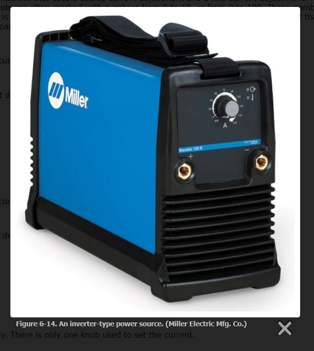
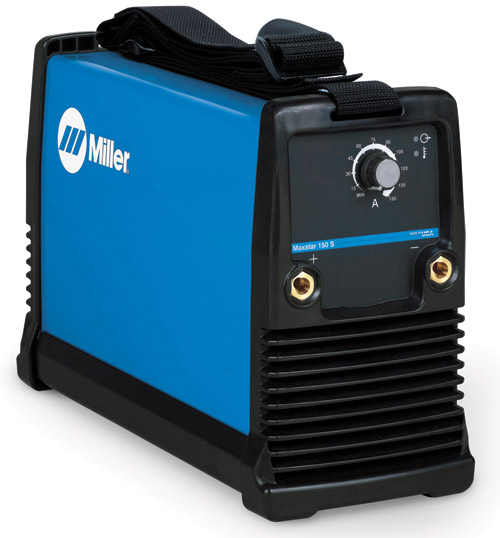
Figure 6-14 is a photo of an inverter power supply. There is only one knob used to set the current.
If the coarse range setting is 100A to 250A, the current delivered = 100A.
Plus
If the fine adjustment is set on 70%, the current delivered is:
70% × current range=current delivered
0.70 × (250−100)A=0.70 × 150A
=105A
Then
Total current delivered=100A + 105A
=205A
Figure 6-14 is a photo of an inverter power supply. There is only one knob used to set the current.
