5.2 Constant Current Power Sources
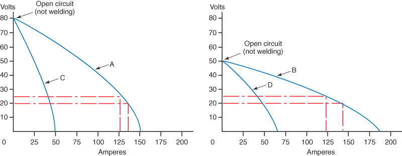
Arc welding power sources are designed to produce an output that has a nearly constant current or a nearly constant voltage. See Chapter 7 for more information on constant voltage power sources. Figure 5-2 shows a typical volt-ampere curve for a constant current power source. Notice the relatively steep slope or “droop” of this curve. Welding machines that have a steep volt-ampere curve are known as droop curve machines or droopers.
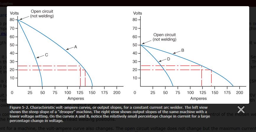
The arc voltage varies with the size or length of the arc gap. Examining Figure 5-2, you see a steeply sloping volt-ampere curve A in the left view. The open circuit voltage, or the voltage when not welding, has been set to 80V.
When the welder strikes the arc and holds it at a certain arc length, the welding voltage or closed circuit voltage is shown as 20V. This arc length produces 135A. See curve A in Figure 5-2. If the welder moves the electrode away from the base metal, the arc length increases and the voltage increases from 20V to 25V. This is a 25% increase in voltage. This change in voltage causes a decrease in welding current. The welding current decreases from 135A to 126A. This is a decrease of only 6.7%. With a large change in voltage, there is only a small change in current and the weld quality is maintained. The current in this machine, even though it varies somewhat, is considered constant.
A constant current power source machine is desired when performing manual arc welding. The two manual arc welding processes are shielded metal arc welding (SMAW) and gas tungsten arc welding (GTAW). Information on GTAW will be covered in Chapter 7.
A different power source has an open circuit voltage of 50V. A volt-ampere curve for this machine is shown as curve B in the right view of Figure 5-2. The same 20V to 25V change in the welding voltage will result in a drop in current from 143A to 124A or 13.3%. This slower-sloping volt-ampere curve output causes a larger change in amperage with the same small change in voltage. A welder may wish to have this slower-sloping (flatter) volt-ampere output curve.
With a flatter output slope, the welder can control the molten weld pool and electrode melt rate by making small changes in the arc length. Control of the molten weld pool and electrode melt rate are most important when welding in the horizontal, vertical, and overhead welding positions.
When a welder changes the range of current for a machine, the volt-ampere curve also changes. The open circuit voltage does not change but the maximum current does change. As the maximum current decreases, as shown in curves C and D, the control of the welding current is even less affected by a change in arc length.
5.2.1 Alternating Current Power Sources
Alternating current (ac) power sources are of either the transformer or generator type.
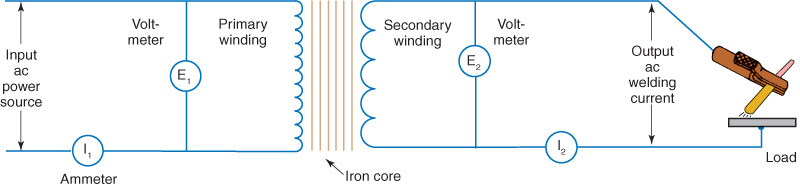
Transformer-Type Power SuppliesThe purpose of a transformer used in a welding machine is to change high-voltage, low-current electricity supplied at the outlet into the lower voltages and higher currents required for welding. Transformers are constructed of three principal electrical components. They are a primary winding, a secondary winding, and an iron core. See Figure 5-3.
Transformer-Type Power SuppliesThe purpose of a transformer used in a welding machine is to change high-voltage, low-current electricity supplied at the outlet into the lower voltages and higher currents required for welding. Transformers are constructed of three principal electrical components. They are a primary winding, a secondary winding, and an iron core. See Figure 5-3.
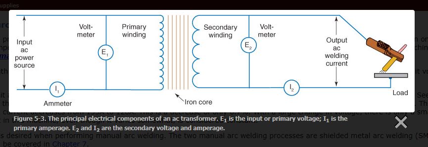
When current flows in a wire, a magnetic field builds up around the wire. When the current stops flowing in the wire, the magnetic field collapses. In a welding transformer, this current-carrying wire is wrapped into a coil with many turns. The more turns there are, the stronger the magnetic field. This coil of wire is called a primary winding or primary coil. A second coil of larger wire with fewer turns is placed next to the primary coil. It is called a secondary winding, or secondary coil. The primary winding and secondary winding are not connected in any way. They are independent coils of wire, but are placed close together.
The primary winding uses thinner wire than the secondary winding, because the primary winding carries less current. There are many more turns in the primary winding than in the secondary winding. When a transformer has more turns in the primary than in the secondary, it decreases the voltage and increases the amperage from the primary to the secondary circuit. This type of transformer is called a step-down transformer. A step-down transformer reduces(steps down) the voltage and increases the current.
To cause a current to flow in the secondary, an alternating current is made to flow in the primary winding. As the current flows, a magnetic field builds up. The current momentarily stops when the alternating current changes direction in the primary circuit. When the current stops, the magnetic field collapses and passes across the secondary winding. This collapse of the field induces (creates) a current in the secondary winding in one direction. Current in the primary winding begins to flow in the opposite direction. It builds a magnetic field and collapses when the current stops to change direction again. The collapsing magnetic field of the primary winding again passes across the secondary winding. A current is induced in the opposite direction. The process of inducing a current in the secondary winding takes place at the rate of 120 times per second, creating an alternating current.
A laminated iron core is used as the center for both the primary and secondary windings. Its purpose is to keep the magnetic field from wandering too far from the windings. If the primary and secondary windings are moved away from one another, the amount of current induced into the secondary decreases, because less of the magnetic field crosses the secondary winding.
