3.5 The Welding Symbol
The welding symbol described on the following pages was developed by the American National Standards Institute (ANSI) and the American Welding Society (AWS). It is described in detail in the publication ANSI/AWS A2.4, Standard Symbols for Welding, Brazing, and Nondestructive Examination.
The entire symbol, as shown in Figure 3-21 with all of its numbers and other symbols, is called the welding symbol. Welding symbols are used on drawings of parts and assemblies which are joined together by welding. A welding symbol may appear in any view on the drawing. Whenever two or more pieces are joined by welding, the assembled item is called a weldment. When the pieces of a weldment are assembled, the lines along which their edges and surfaces come in contact are called joints.
The drawing of a weldment seldom shows how the edges are to be prepared or how the completed weld appears. The drawing shows only how the parts come together and what type of joint they will form. Occasionally, when an unusual or very complex weld joint is to be made, a “detail” drawing of the joint may be drawn with the joint preparation and weld shape shown and dimensioned. Refer to Figure 3-1 for the types of welded joints and the types of welds used on the various joints.
A complete welding symbol contains all the information about a welded joint. The welding symbol may appear in any view of the drawing. A welding symbol applies to only one joint and applies to that joint only until it changes direction. There are a few exceptions to this rule—they will be discussed later in this chapter. Some of the following information is given to the welder on the welding symbol:
- How to prepare the edges of the base metal prior to welding.
- What welding process to use.
- What type of weld to make.
- Where to place the weld.
- The size of the weld.
- The shape of the weld face.
- How to finish the weld surface after welding is completed.
Much more information regarding the weld is also given on the welding symbol. Dimensions on a welding symbol may be in SI Metric units or US Customary units of measurement.
Part of the complete welding symbol is the weld symbol, which shows what type of weld is to be placed in a joint. See Figure 3-21 for the position of the weld symbol within the overall welding symbol. Figure 3-22 shows the weld symbols used on an ANSI/AWS welding symbol.
Information given in each part or area of the welding symbol will be explained in later paragraphs. A number of weld drawings, with their corresponding welding symbols, will be shown to illustrate the information given in the various areas of the complete welding symbol. The edges of the weld joint, as they would be prepared and fitted up prior to welding, will be shown using hidden lines. A completed weld for the welding symbol will also be shown.
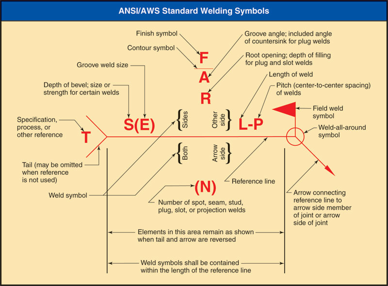
Figure 3-21.
Specific locations have been assigned on the welding symbol for various information and sizes. (AWS A2.4:2012, Figure 3, Standard Location of the Elements of a Welding Symbol, reproduced with permission from the American Welding Society, Miami, Fl).
Specific locations have been assigned on the welding symbol for various information and sizes. (AWS A2.4:2012, Figure 3, Standard Location of the Elements of a Welding Symbol, reproduced with permission from the American Welding Society, Miami, Fl).
Figure 3.21
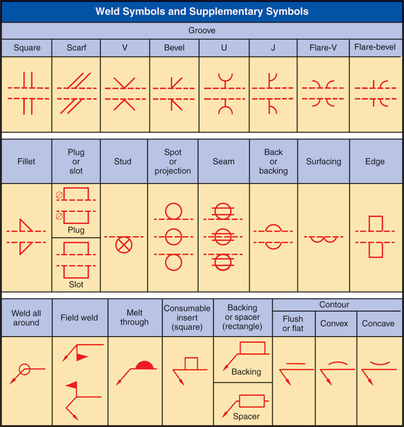
Figure 3-22.
Weld symbols and supplementary symbols. These may be part of the complete welding symbol. (AWS A2.4:2012, Figure 1, Weld Symbols, and Figure 2, Supplementary Symbols, reproduced with permission from the American Welding Society, Miami, Fl)
Weld symbols and supplementary symbols. These may be part of the complete welding symbol. (AWS A2.4:2012, Figure 1, Weld Symbols, and Figure 2, Supplementary Symbols, reproduced with permission from the American Welding Society, Miami, Fl)
