3.3 Joint Geometry
The American Welding Society defines joint geometry as “the shape and dimensions of a (weld) joint, in cross section, prior to welding.” Joint geometry is generally determined by a welding engineer or designer. The assembly design and the dimensions of a joint depend on the metal thickness and shape and on the load requirements of the parts. The parts are prepared to ensure that the weld will have adequate penetration. The joint geometry design also provides space for the welder to reach near the bottom of the weld joint with the torch or electrode.
3.3.1 Preparation
The edges of thick metal are prepared for welding by flame cutting, gouging, or machining. Preparation allows the weld to penetrate as deep as required by the engineer or weld designer. A groove joint allows the welder to reach the bottom of the weld joint. The groove angle must be large enough to allow the torch tip or electrode to reach near the bottom of the joint. However, if the groove angle is too large, filler metal and the welder's time are wasted. This increases the cost of making a weld. See Figure 3-12A. A properly designed J-groove or U-groove joint also decreases the groove dimensions while allowing adequate space for welding. See Figure 3-12B.

3.3.2 Joint Alignment
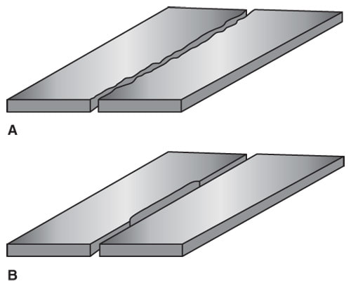
The alignment of a joint before welding is very important. In the shop, the alignment of the weld joint is often referred to as “fit-up.” A ragged edge or an edge that is not cut straight is hard to weld. See Figure 3-13. Edges to be welded must be straight and cut to exact size.
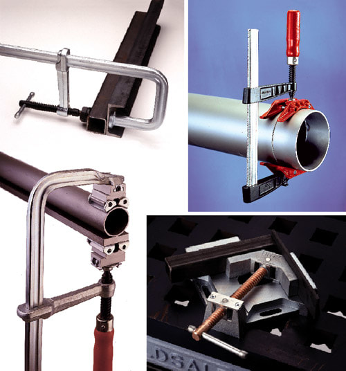
Parts of a weldment should be properly aligned and held in position during the welding operation. Tack welding is usually adequate to hold parts during welding. A tack weld is a small weld used to hold pieces in alignment. Parts may also be held mechanically during the welding operation because the metal expands, bends, and changes shape when heated. Clamps or other devices, such as jigs and fixtures, are used to hold weldments during welding. See Figure 3-14.
Parts of a weldment should be properly aligned and held in position during the welding operation. Tack welding is usually adequate to hold parts during welding. A tack weld is a small weld used to hold pieces in alignment. Parts may also be held mechanically during the welding operation because the metal expands, bends, and changes shape when heated. Clamps or other devices, such as jigs and fixtures, are used to hold weldments during welding. See Figure 3-14.
3.3.3 Penetration
A completed weld joint must be at least as strong as the base metal. The weld must penetrate deeply into the base metal to be strong. Penetration is the depth of fusion of the weld below the surface. Total (100%) penetration occurs when a weld penetrates through the entire thickness of the base metal. Generally, total penetration is required only on a butt joint. The edges of thick metal may need to be machined or flame cut to achieve 100% penetration. Thick metal also may have to be welded from both sides of the joint.
