3.1 Basic Weld Joints
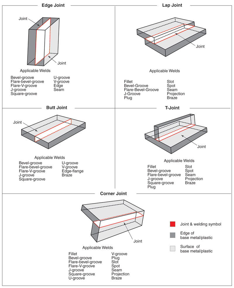
Figure 3.1
Figure 3-1
Figure 3-1. Basic welding joint designs. Note that there are only five basic joints, but that many types of welds can be placed on each type of joint. (AWS A3.0:2010, Figure 1, Joint Types, reproduced with permission from the American Welding Society, Miami, Fl.)
Basic Weld Joints
A weld joint refers to how the parts to be joined are assembled prior to welding. There are five basic types of joints used in welding: butt, lap, corner, T-, and edge. See Figure 3-1.
The metal to be joined is called the base metal. If the part to be welded is not metal, it is called base material. It is also known as the workpiece or work. The edges of the base metal are often machined, sheared, gouged, flame cut, or bent to prepare them for welding. Weld joint design and metal thickness usually determine how the joint is prepared. Generally, the weld joint design is determined by an engineer.
