14.9 Automatic Cutting
Automatic cutting machines are constantly being improved. Cutting processes such as metal powder cutting (POC), plasma arc cutting (PAC), flux cutting (FOC), air carbon arc (CAC–A), exothermic cutting, and water jet cutting are often done using automatic machines.
Automatic cutting equipment requires a controller or a computer to control the operation. The cutting process is completely controlled and does not require adjustment while cutting. The controller or computer is programmed with the path and speed of the torch or torches. Solenoid valves start and stop the flow of gases. Electric motors, actuated by the controller or computer, are used to very precisely control the movement of the torch or torches. Because of these features, automatic cutting equipment produces almost identical parts every time.
Feedback controls monitor the automatic cutting process and make necessary corrections. Feedback control items may include vision devices. These vision devices are used to keep the preheating flames at a specified height above the base metal at all times.
Semiautomatic cutting, or mechanized cutting, is similar to automatic cutting except that some changes to the process may be required while cutting is taking place. These processes often use electronic and magnetic tracers to follow a pattern. As the pattern is followed, electric motors move the torch or torches to cut the metal in the same shape as the pattern. Electronic tracers permit a pattern to be followed so that extremely accurate shapes can be produced. Chapter 25 describes semiautomatic and automatic processes.
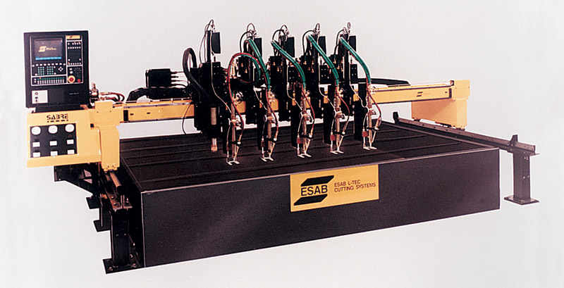
There are many automatic and semiautomatic mechanisms available to perform cutting operations. Multiple-torch cutting machines are used extensively in industry. They cut several exact copies of a desired part at one time. Figure 14-37 shows automatic cutting equipment. Inexpensive metal templates or line drawings can be used to guide mechanical or electronic tracers. Practically all pattern tracers and automatic cutting machines and their torches are moved by variable speed electric motors known as servomotors.
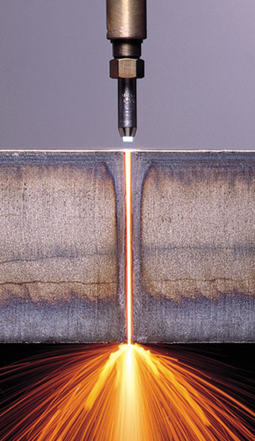
Special cutting torches are mounted on a light, rigid rail. These cutting torches, Figure 14-38, can be adjusted to vary the flame tip-to-metal surface distance. This rail, with all its mechanisms, is called a gantry. Both rail and torches are moved on the X-Y (lateral and longitudinal) axes by electric servomotors. As the tracer moves around the pattern, the servomotors move the rail and torches to duplicate the pattern. A servomotor gets feedback information from the pattern tracer. This feedback causes the servomotor to move the rail and torches in the proper direction to duplicate the pattern.
Automatic cutting equipment requires a controller or a computer to control the operation. The cutting process is completely controlled and does not require adjustment while cutting. The controller or computer is programmed with the path and speed of the torch or torches. Solenoid valves start and stop the flow of gases. Electric motors, actuated by the controller or computer, are used to very precisely control the movement of the torch or torches. Because of these features, automatic cutting equipment produces almost identical parts every time.
Feedback controls monitor the automatic cutting process and make necessary corrections. Feedback control items may include vision devices. These vision devices are used to keep the preheating flames at a specified height above the base metal at all times.
Semiautomatic cutting, or mechanized cutting, is similar to automatic cutting except that some changes to the process may be required while cutting is taking place. These processes often use electronic and magnetic tracers to follow a pattern. As the pattern is followed, electric motors move the torch or torches to cut the metal in the same shape as the pattern. Electronic tracers permit a pattern to be followed so that extremely accurate shapes can be produced. Chapter 25 describes semiautomatic and automatic processes.
There are many automatic and semiautomatic mechanisms available to perform cutting operations. Multiple-torch cutting machines are used extensively in industry. They cut several exact copies of a desired part at one time. Figure 14-37 shows automatic cutting equipment. Inexpensive metal templates or line drawings can be used to guide mechanical or electronic tracers. Practically all pattern tracers and automatic cutting machines and their torches are moved by variable speed electric motors known as servomotors.
Special cutting torches are mounted on a light, rigid rail. These cutting torches, Figure 14-38, can be adjusted to vary the flame tip-to-metal surface distance. This rail, with all its mechanisms, is called a gantry. Both rail and torches are moved on the X-Y (lateral and longitudinal) axes by electric servomotors. As the tracer moves around the pattern, the servomotors move the rail and torches to duplicate the pattern. A servomotor gets feedback information from the pattern tracer. This feedback causes the servomotor to move the rail and torches in the proper direction to duplicate the pattern.

|

|
Once set up, these cutting machines are self-operating. However, the initial adjustments must be very carefully made by the operator:
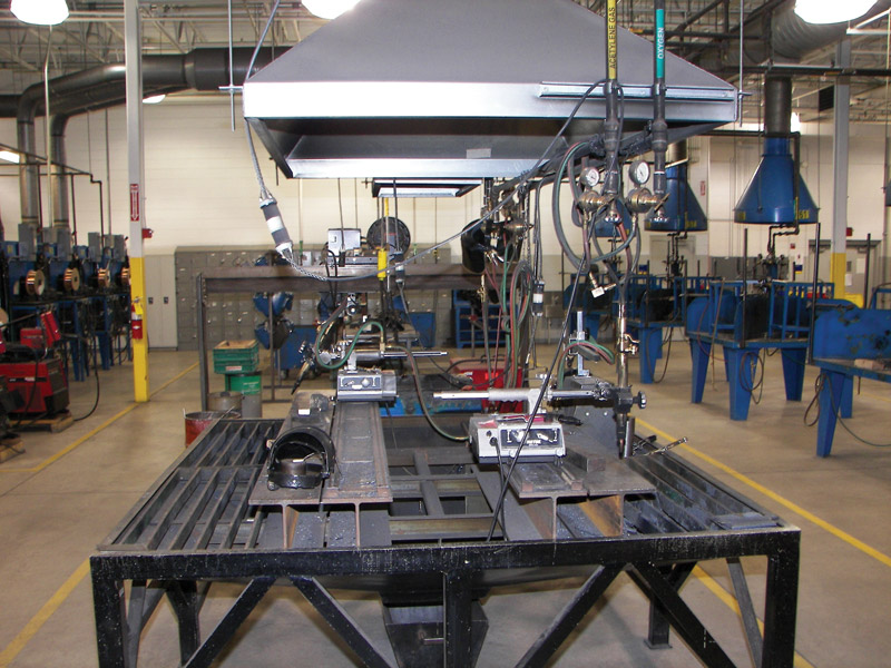
In addition to properly setting up and adjusting the machine, the operator must periodically inspect and perform maintenance on its critical parts, such as cutting tips. Most welding schools have a designated cutting area that has a motorized carriage for students to use in practicing how to properly set up and make adjustments to the cutting outfit. See Figure 14-39.
- Adjustment for the number of in/min (cm/min) to be cut.
- Gas pressure must be carefully adjusted to ensure a clean cut through the thickness of the metal without wasting fuel.
- Flames should be adjusted so each torch produces an identical cut.
- Distance of the torch tip from the metal being cut must be carefully adjusted to obtain the best results. This adjusting is done by means of a graduated scale on the torch body, and a vernier gear mechanism (measuring device that permits fine adjustment), to raise and/or lower the torch.
In addition to properly setting up and adjusting the machine, the operator must periodically inspect and perform maintenance on its critical parts, such as cutting tips. Most welding schools have a designated cutting area that has a motorized carriage for students to use in practicing how to properly set up and make adjustments to the cutting outfit. See Figure 14-39.

Figure 14-39
Figure 14-39. This welding school has a well-ventilated oxyfuel gas cutting area complete with motorized carriages for student practice.
Figure 14-39. This welding school has a well-ventilated oxyfuel gas cutting area complete with motorized carriages for student practice.
A magnetic tracer with a steel pattern can be used as a cutting torch guiding device. The tracer, driven by a small, adjustable motor, rotates and follows the pattern. Cutting torches, or torches, are normally mechanically attached to the tracer mechanism. As the tracer moves, the torches move in the same pattern to cut the metal. The speed of cutting is determined by the speed of rotation of the pattern tracer. The variable-speed motor on the tracer must be manually set. It allows the tracer and the cutting torches to move at the correct speed for the thickness of metal being cut.
