14.5 Using a Cutting Torch
The cutting torch must be used carefully in order to create clean and accurate cuts. The tip must be in excellent condition and set to align properly with the cutting line. See Figure 14-6. The preheating flames must be correctly adjusted, and the cutting oxygen pressure must be correct.
To cut, bring the tip of the inner cone of the preheating flames to the edge of the metal to be cut. The cutting torch should be held so that the inner cone of the preheat flames is about 1/16″ to 1/8″ (1.6mm to 3.2mm) from the surface of the metal being cut, as shown in Figure 14-13.
To cut, bring the tip of the inner cone of the preheating flames to the edge of the metal to be cut. The cutting torch should be held so that the inner cone of the preheat flames is about 1/16″ to 1/8″ (1.6mm to 3.2mm) from the surface of the metal being cut, as shown in Figure 14-13.
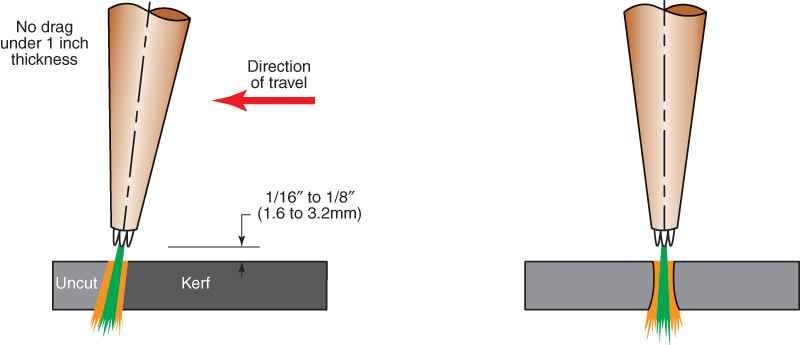
Figure 14-13
Figure 14-13. The cutting torch position used for cutting with the oxyfuel gas cutting torch. The cutting head and tip are tilted away from the direction of cutting at a 5°–20° angle from vertical.
Figure 14-13. The cutting torch position used for cutting with the oxyfuel gas cutting torch. The cutting head and tip are tilted away from the direction of cutting at a 5°–20° angle from vertical.
As soon as a spot on the cutting line has been heated to a bright cherry red color, open the cutting oxygen valve all the way. The jet of oxygen coming through the center of the tip (oxygen jet) causes the heated metal to burn (oxidize) away, forming the kerf (cut).
One of the best indications of a good cutting operation is the appearance of the slag stream at the bottom of the cut. The ideal slag stream passes directly through a plate less than 1″ (25.4mm) thick. When cutting steel plates thicker than 1″ (25.4mm), some drag is desirable to ensure the proper amount of oxygen is consumed. This results in an even cut.
Drag is a measurement, made in the direction of travel, between the entry and exit points of the cutting jet. See Figure 14-14. If the slag stream lags excessively behind the torch tip travel, the following are possible causes:
- The flame adjustment may be incorrect.
- The cutting oxygen pressure adjustment may be too low.
- The tip travel is too fast and the metal is not being preheated enough.
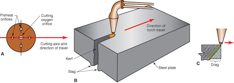
Figure 14-14
Figure 14-14. An oxyacetylene cut in progress. A—Note the slag at the bottom of the kerf. B—Cut in progress with some slag at the bottom of the plates. C—Cutting oxygen slows down as it travels through the metal. Drag results from the oxygen slowing down and the forward motion of the torch.
Figure 14-14. An oxyacetylene cut in progress. A—Note the slag at the bottom of the kerf. B—Cut in progress with some slag at the bottom of the plates. C—Cutting oxygen slows down as it travels through the metal. Drag results from the oxygen slowing down and the forward motion of the torch.
14.5.1 Cutting Attachments
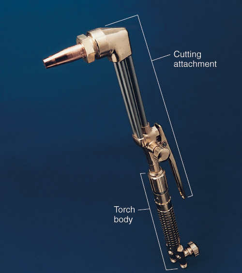
Most manufacturers of oxyfuel gas welding and cutting torches market a cutting attachment. The attachment is connected to the welding torch body to change the torch from a welding torch to a cutting torch. Review Heading 14.4 for more information on cutting torch attachments. The cost of such an attachment and the welding torch is usually less than the cost of a separate welding torch and a cutting torch. For portable kits, this attachment saves space. To connect a cutting attachment, remove the welding tip tube and screw on the cutting attachment.
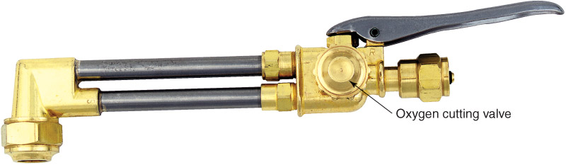
The operation of the torch with the cutting attachment is the same as the operation of a regular cutting torch. Figure 14-3 shows a cutting attachment and Figure 14-15 shows a cutting attachment installed on a torch body. There are usually two torch oxygen valves, one torch acetylene valve, and a cutting oxygen lever involved when a cutting attachment is used. The welding torch body has an oxygen valve and a torch acetylene valve. The cutting attachment has a torch oxygen valve and a cutting oxygen lever.
To make flame adjustments, the torch oxygen valve on the cutting attachment should be opened one or more turns. The torch valves on the torch body are then used to adjust the flames.
Caution: The torch valves on the welding torch body must be turned off before the cutting attachment is disconnected.

|

|
14.5.2 Cutting Tips
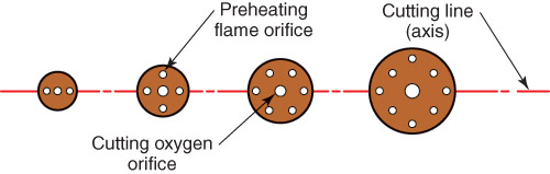
Cutting tips normally have at least two orifices. One orifice, which is usually in the center of the tip, is for the cutting oxygen. One or more smaller orifices are for preheating the metal to be cut.
Cutting tips can be made of one-piece or two-piece construction. One-piece tips are used for oxyacetylene cutting only. Two-piece tips are used for all other gas cutting: natural gas, propane, LP gas mixes, etc.
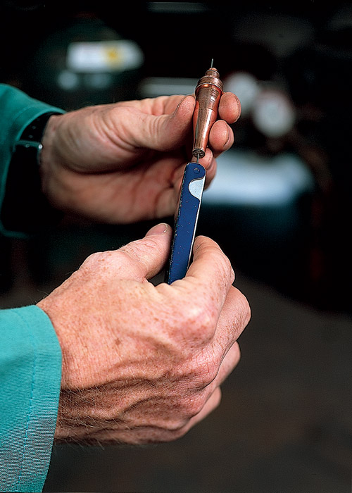
For satisfactory service, tips must be kept in good condition. The orifice end must be clean. See Figure 14-16. The tip surface must be clean and at a right angle to the orifice passages, so that the preheat flame is shaped and aimed properly. The sealing faces of the tip, (which contacts the torch body) must be clean and free from scratches, burrs, nicks, etc., or these joints may leak. Clean the tips as described in Chapter 13.
Always store the extra tips in soft holders. A wooden block with holes drilled in it works well. See Chapter 13 for more detailed information about tip cleaning and care.
Cutting tips can be made of one-piece or two-piece construction. One-piece tips are used for oxyacetylene cutting only. Two-piece tips are used for all other gas cutting: natural gas, propane, LP gas mixes, etc.
For satisfactory service, tips must be kept in good condition. The orifice end must be clean. See Figure 14-16. The tip surface must be clean and at a right angle to the orifice passages, so that the preheat flame is shaped and aimed properly. The sealing faces of the tip, (which contacts the torch body) must be clean and free from scratches, burrs, nicks, etc., or these joints may leak. Clean the tips as described in Chapter 13.
Always store the extra tips in soft holders. A wooden block with holes drilled in it works well. See Chapter 13 for more detailed information about tip cleaning and care.
