11.6 Oxyacetylene Torch Types
A welding torch (sometimes called a “blowpipe”) and a cutting torch (sometimes incorrectly called a “burning torch”) are each designed for a specific purpose. These torches are somewhat similar in construction, but a cutting torch is provided with a separate control valve to regulate an oxygen jet for the cutting. These torches come in a variety of sizes and designs, depending on their intended use. See Chapters 13 and 14 for additional information.
There are two types of welding and cutting torches commonly used. They are the positive-pressure type (also known as an equal-pressure type or medium-pressure type torch), and the injector type.
There are two types of welding and cutting torches commonly used. They are the positive-pressure type (also known as an equal-pressure type or medium-pressure type torch), and the injector type.
11.6.1 Positive-Pressure Welding Torches
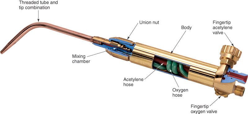
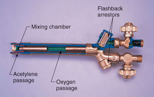
In a positive-pressure torch, oxygen and fuel gas are mixed in the torch and are burned at the end of the torch tip. The torch consists of four main parts, as shown in Figure 11-42.
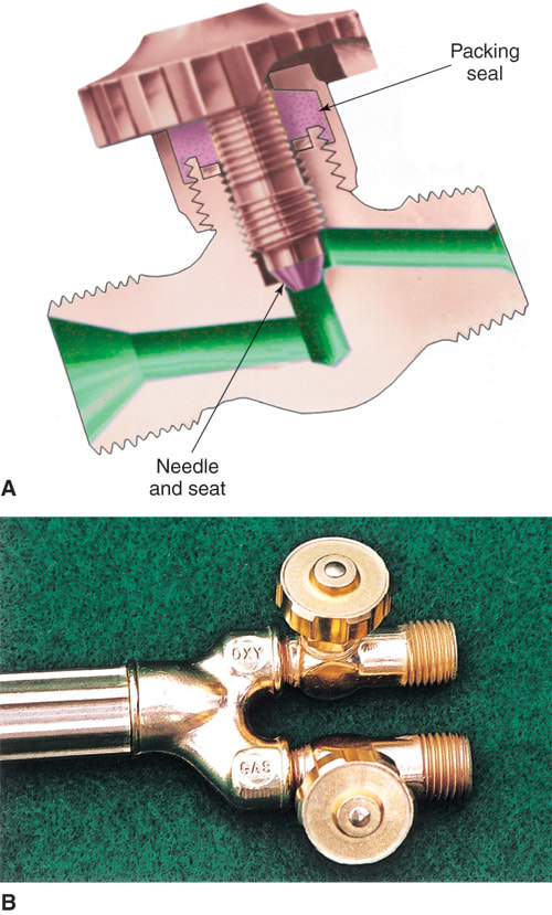
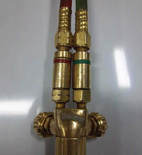
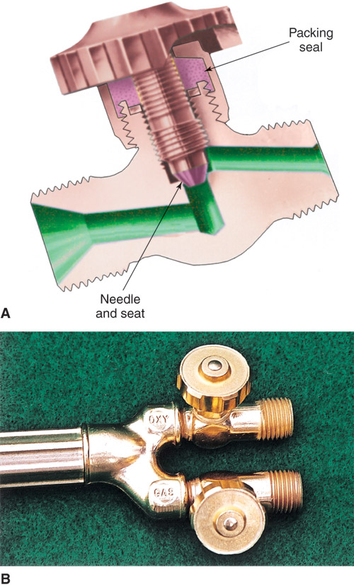
The hand valves are located either at the end of the torch where the hoses attach to the torch body, as shown in Figure 11-40, or at the tip end of the torch body as shown in Figure 11-45. The torch valves are generally either a needle-and-seat or ball-and-seat design, as shown in Figure 11-46. Hand valves are used chiefly for shutting off the gas and turning it on; however, many welders use them to throttle(make the final flow adjustment to) the gases being fed to the torch.
- Body.
- Hand torch valves.
- Mixing chamber.
- Tip.
The hand valves are located either at the end of the torch where the hoses attach to the torch body, as shown in Figure 11-40, or at the tip end of the torch body as shown in Figure 11-45. The torch valves are generally either a needle-and-seat or ball-and-seat design, as shown in Figure 11-46. Hand valves are used chiefly for shutting off the gas and turning it on; however, many welders use them to throttle(make the final flow adjustment to) the gases being fed to the torch.

|

|
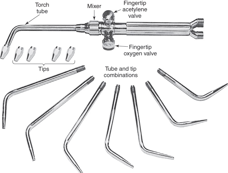
Figure 11-47 illustrates the construction of a medium-duty positive-pressure welding torch. Figure 11-45 shows a light-duty torch with different tips.
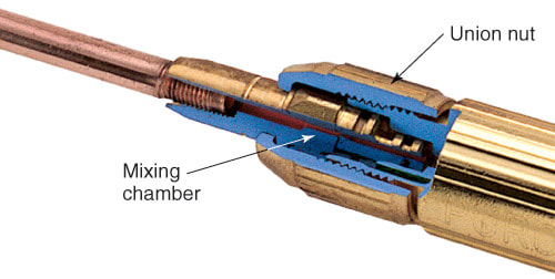
The mixing chamber is usually located inside the torch body, although some torches incorporate the mixing chamber in the torch tube. Gases are fed to this chamber through two brass or stainless steel tubes leading from the torch valves. The size and design of the mixing chamber depends on the size of the torch. Some torch designs change the size and shape of the mixing chamber at the same time the tip is changed. Orifices and the chambers should never be abused.
The orifice, or hole drilled in the tip, must be an accurate size. The tip size or number is normally stamped on the tip. The tip number indicates the orifice size and the relative volume of gases that it will allow to flow through the tip. The tips are usually made of copper, but some tips are nickel-plated to reflect heat and stay cooler. In this text, torch tip size is indicated by number drill sizes.
11.6.2 Injector-Type Welding Torches
An injector (low-pressure) welding torch looks much like a positive-pressure torch. However, the internal construction of an injector torch is somewhat different. The chief characteristic of an injector torch is its ability to operate using very low acetylene pressure. In general, the acetylene pressure remains practically constant regardless of the size tip or thickness of the metal being welded.
The ability of this torch to operate on low acetylene pressure has certain advantages. If acetylene is being supplied by a low-pressure acetylene generator, which supplies acetylene at a pressure of approximately 1/4 psig (1.7kPa), an injector torch must be used. An injector torch also has the advantage of being able to draw out the last remnants of acetylene from a cylinder, which a positive pressure torch is unable to do. This reduces waste.
The ability of this torch to operate on low acetylene pressure has certain advantages. If acetylene is being supplied by a low-pressure acetylene generator, which supplies acetylene at a pressure of approximately 1/4 psig (1.7kPa), an injector torch must be used. An injector torch also has the advantage of being able to draw out the last remnants of acetylene from a cylinder, which a positive pressure torch is unable to do. This reduces waste.
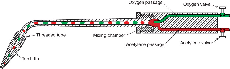
Figure 11-48 shows the internal construction of the mixing chamber portion of an injector-type welding torch. The oxygen line enters the mixing chamber through a jet which is surrounded by the acetylene passage. As the oxygen flows from the jet, it draws (injects) the acetylene along with it. Handling the valves and the other operations of the torch is much the same as with the positive-pressure type torch. It should be noted that the oxygen pressure used in these torches is considerably higher than with the positive-pressure type torches. Follow the torch adjustments recommended by the torch manufacturer. The materials used to construct injector-type torches are usually the same as those materials used to construct positive-pressure torches.
|

|
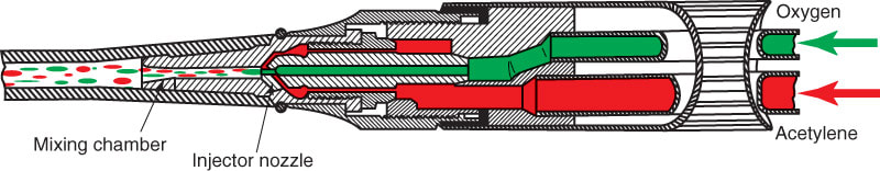
Figure 11-48
Figure 11-48. Cross-sectional view of the mixing chamber area of an injector-type welding torch. The acetylene is injected (drawn) into the mixing chambers by the venturi (pulling) action of the oxygen jet. Injector torches are particularly adaptable for use with acetylene generators, which operate under low-pressure.
Figure 11-48. Cross-sectional view of the mixing chamber area of an injector-type welding torch. The acetylene is injected (drawn) into the mixing chambers by the venturi (pulling) action of the oxygen jet. Injector torches are particularly adaptable for use with acetylene generators, which operate under low-pressure.
