11.4 Pressure Regulator Principles
Gases are commonly stored in cylinders under high pressure. This high pressure is referred to as cylinder pressure. Most welding torches operate at pressures between 0 psig and 30 psig (0kPa and 207kPa). This reduced pressure is referred to as working pressure. A pressure regulator is a mechanism installed between the cylinder and the torch lines to reduce and stabilize gas pressure. Without a pressure regulator, equipment would be damaged and welding would be impossible. Every system that requires the control of gas pressure uses a pressure regulator.
The regulator performs two functions:
The regulator performs two functions:
- It reduces the pressure of gas leaving the cylinder.
- It maintains a constant working pressure at the torch even though the cylinder pressure may vary.

There are two basic types of regulator mechanisms: the nozzle-type and the stem-type. Figure 11-21 shows the construction of a nozzle-type regulator. Figure 11-22 shows a cross section of a stem-type regulator. Figure 11-23 shows a typical oxyfuel gas welding outfit with regulators in place on each cylinder.
|
|
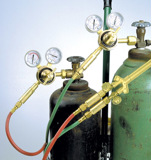
Figure 11-23
Figure 11-23. An oxyfuel gas welding outfit with oxygen and acetylene regulators properly connected and ready for use. (Victor, a division of Thermadyne Industries, Inc.)
Figure 11-23. An oxyfuel gas welding outfit with oxygen and acetylene regulators properly connected and ready for use. (Victor, a division of Thermadyne Industries, Inc.)
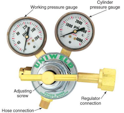
Most regulators have two gauges. The high-pressure gauge shows the cylinder pressure. The low-pressure gauge shows the working pressure, or the pressure of the gas being delivered to the torch.
Two varieties of regulators are available:
Two-stage regulators provide more accurate pressure control and readings. A single-stage regulator must drop the pressure in one large step from 2000 psi to a working pressure of 3–20 psi so it is not as well-regulated. A two-stage regulator is more accurate and better regulated. By reducing the pressure to a lower level in two steps, a more precise reduction of pressure results.
Two varieties of regulators are available:
- Single-stage regulators, which reduce the cylinder pressure to a working pressure in one step. Example—2000 psig to 5 psig (13790kPa to 34.5kPa).
- Two-stage regulators, which reduce the cylinder pressure to working pressure in two steps or stages. Example—2000 psig to 200 psig (13790kPa to 1379kPa), then 200 psig to 5 psig (1379kPa to 34.5kPa).
Two-stage regulators provide more accurate pressure control and readings. A single-stage regulator must drop the pressure in one large step from 2000 psi to a working pressure of 3–20 psi so it is not as well-regulated. A two-stage regulator is more accurate and better regulated. By reducing the pressure to a lower level in two steps, a more precise reduction of pressure results.
Regulator bodies are generally forged or cast and are made of brass, aluminum, or stainless steel. The regulator's pressure gauges are threaded into the regulator body. A pressure relief valve is also threaded into the regulator body. If the pressure within the regulator becomes too high, the relief valve will vent the pressure so that the regulator does not rupture.
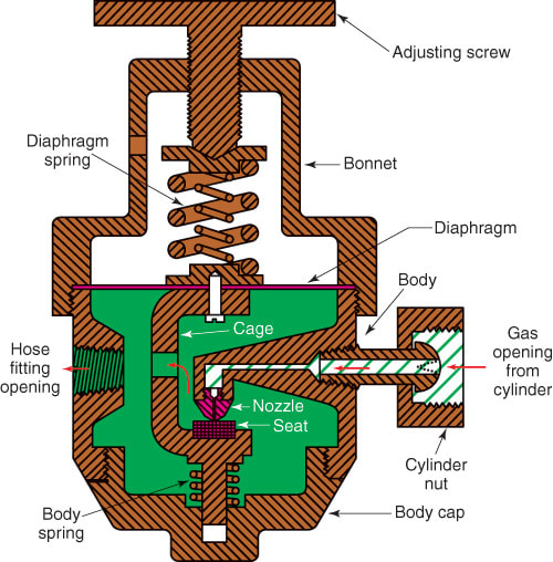
11.4.1 Nozzle-Type Pressure Regulators
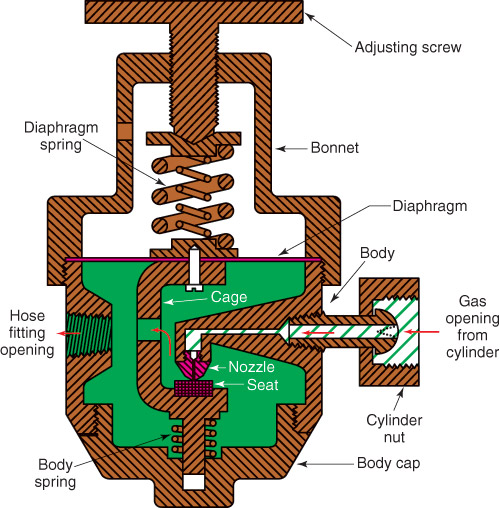
See Figure 11-21 for an illustration of a nozzle-type pressure regulator. A fitting to attach the regulator to the cylinder is threaded into the body. The regulator body generally has threaded openings for a high-pressure gauge and a low-pressure gauge. Line regulators, used with manifold gas supplies, may have only one opening for a low-pressure gauge. An additional opening is used to connect the torch hose to the regulator's low-pressure outlet.
A diaphragm or flexible disc separates and seals the body from the bonnet. The diaphragm spring is mounted between the diaphragm and the adjusting screw. Force on the diaphragm is adjusted by means of an adjusting screw. A cage or carrier is attached to the body side of the diaphragm. This cage curves down into the regulator body chamber. The seat is attached to the cage near the bottom of the body chamber. This seat is constantly pushed toward the nozzle by the body spring.
The gap between the nozzle and seat is controlled by the position of the diaphragm. The line that leads to the nozzle comes from the cylinder and has a port for attaching a high-pressure gauge. A fine mesh screen or ceramic filter is commonly located in this line. This filter keeps dirt from entering and damaging the regulator. The screen also serves as a flame arrestor and should always be left in place.
If the adjusting screw in the body is turned “in” (clockwise), the diaphragm spring on the bonnet side of the diaphragm will overcome the force of the body spring. The diaphragm spring will then move the seat away from the nozzle, allowing some gas to pass from the cylinder into the regulator body. As this gas enters the regulator body, it builds up pressure in the body. The force created by this pressure pushes the diaphragm up against the diaphragm spring. The upward movement of the diaphragm moves the cage and the seat up. This closes off the nozzle opening. The pressure falls as the gas is released from the regulator and flows through the hose to the torch. This action allows the diaphragm spring to move the diaphragm down slightly. The nozzle and seat valve open and allow more gas to come into the regulator body. The balance of the diaphragm spring pushing the diaphragm and seat open, and the pressure under the diaphragm pushing the seat closed, keeps the working pressure flowing through the regulator relatively constant.
Note: The flow of gas from the cylinder is stopped completely when the adjusting screw on the regulator is turned all the way out.
These regulators come in various gas flow capacities and nozzle orifice sizes. The diaphragm, seat orifice, and spring sizes are designed to provide the volume of gas desired. Master regulators are designed to allow a large amount of gas to flow. Line regulators allow the flow of relatively small amounts of gas. The springs are made of a good grade of spring steel, while the diaphragm may be made of brass, phosphor bronze, sheet spring steel, or stainless steel.
The diaphragm is sealed at the joint between the diaphragm and the regulator body by means of suitable gaskets and the clamping action between the body and the bonnet. The nozzle is usually made of bronze, while the seat may be made of various materials such as nylon, Teflon®, neoprene, or some proprietary materials.
The diaphragm is sealed at the joint between the diaphragm and the regulator body by means of suitable gaskets and the clamping action between the body and the bonnet. The nozzle is usually made of bronze, while the seat may be made of various materials such as nylon, Teflon®, neoprene, or some proprietary materials.
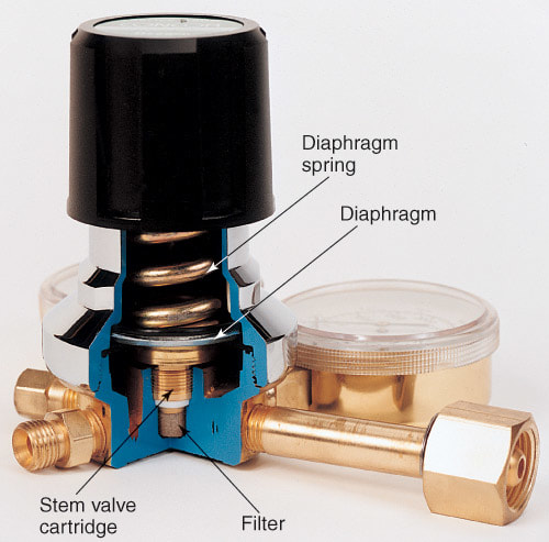
11.4.2 Stem-Type Pressure Regulators
A stem-type regulator works on the same principle as a nozzle-type, but instead of using a nozzle and seat, it employs a poppet valve and seat. Figure 11-22 shows a cutaway view of a typical stem-type regulator.
High-pressure gas enters the chamber below the seat when the cylinder valve is opened. The construction is such that the high pressure and the body spring force the valve against its seat. The regulator's pressure-adjusting screw is turned in to force the diaphragm spring and diaphragm down. The diaphragm pushes the valve stem down. This downward movement forces the valve away from the seat.
As pressure builds below the diaphragm, the diaphragm moves up, closing the valve. Gas from the low-pressure chamber is fed to the torch.
As the pressure in the low-pressure chamber drops, the diaphragm spring forces the diaphragm, stem, and valve down again. This allows more high-pressure gas to enter the low-pressure chamber and shut off the valve again. This constant opening and closing of the valve as the diaphragm moves up and down controls the working (outlet) pressure within close preset limits.
Stem-type regulators are used where a high rate of flow is required. The high rate of flow they provide make these regulators ideal for manifolds and flame cutting machines.
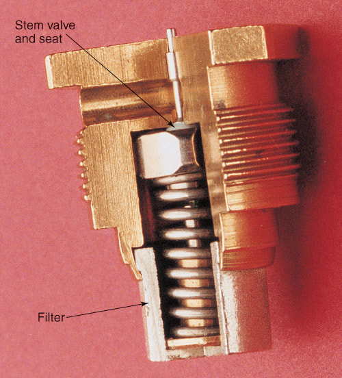
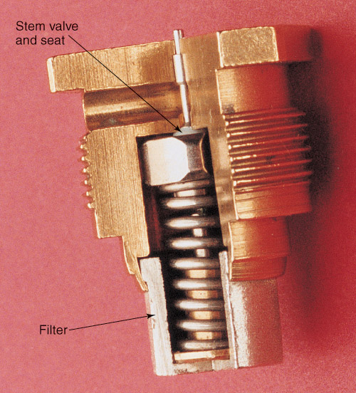
The materials in a stem-type pressure regulator are similar to those used in the nozzle-type regulator. The seat may be constructed of neoprene, Teflon®, or special proprietary materials. The stem (pin) is usually made of stainless steel. The stem and seat may be designed to enable the complete assembly to be removed as a cartridge, permitting easy servicing. Figure 11-24 shows a stem-type valve built as a cartridge.
High-pressure gas enters the chamber below the seat when the cylinder valve is opened. The construction is such that the high pressure and the body spring force the valve against its seat. The regulator's pressure-adjusting screw is turned in to force the diaphragm spring and diaphragm down. The diaphragm pushes the valve stem down. This downward movement forces the valve away from the seat.
As pressure builds below the diaphragm, the diaphragm moves up, closing the valve. Gas from the low-pressure chamber is fed to the torch.
As the pressure in the low-pressure chamber drops, the diaphragm spring forces the diaphragm, stem, and valve down again. This allows more high-pressure gas to enter the low-pressure chamber and shut off the valve again. This constant opening and closing of the valve as the diaphragm moves up and down controls the working (outlet) pressure within close preset limits.
Stem-type regulators are used where a high rate of flow is required. The high rate of flow they provide make these regulators ideal for manifolds and flame cutting machines.
The materials in a stem-type pressure regulator are similar to those used in the nozzle-type regulator. The seat may be constructed of neoprene, Teflon®, or special proprietary materials. The stem (pin) is usually made of stainless steel. The stem and seat may be designed to enable the complete assembly to be removed as a cartridge, permitting easy servicing. Figure 11-24 shows a stem-type valve built as a cartridge.
