11.11 Oxyfuel Gas Welding Supplies
Many supplies are needed in order to perform the usual oxyfuel gas welding operations. The more common supplies needed are:
Note: Keep oil, grease, and other petroleum products away from the welding area. They are highly combustible in the presence of oxygen and could spontaneously combust.
- Welding gases, consisting of oxygen and fuel gas.
- Welding rod (filler metal) for steel, stainless steel, cast iron, aluminum, and hardfacing.
- Fluxes for cast iron welding, aluminum welding, stainless steel welding, or soldering and brazing. See Chapters 15 and 16.
- Firebrick.
- Carbon paste and forms.
Note: Keep oil, grease, and other petroleum products away from the welding area. They are highly combustible in the presence of oxygen and could spontaneously combust.
11.11.1 Other Fuel Gases
Acetylene is the most commonly used fuel gas for welding. Other fuel gases commonly used are:
- Hydrogen.
- LP (liquefied petroleum), propane, and butane.
- Natural gas.
- Polypropylene-based fuel gas (FG–2).
No other fuel gas mixed with oxygen has a flame temperature as high as the oxyacetylene flame. The oxyhydrogen flame, however, is very clean and is recommended for welding aluminum and magnesium. Because hydrogen can be used at a higher pressure than acetylene, it has also been used for underwater welding and cutting. Since hydrogen is a reducing agent, the oxyhydrogen flame minimizes oxidation, if properly adjusted. A regular oxyacetylene torch can be used with hydrogen as the fuel gas. Hydrogen is supplied in cylinders, as is oxygen. The pressures in oxygen and hydrogen cylinders are about the same. The standard sizes of hydrogen cylinders are 200 ft3(5663L) and 100 ft3 (2832L).
Hydrogen cylinders are fitted with special fittings, so the regulators used on these cylinders require proper mating attachments. Hydrogen has no odor, and when combined with either air or oxygen in the proper proportions, it forms a powerful explosive mixture. Hydrogen connections should be regularly checked for leaks using a soap-and-water solution. Leak detection will be covered in Chapter 12.
Liquefied petroleum (LP) is sold under a variety of names and can have a variety of chemical compositions. For welding use, the general title of liquefied petroleum (LP) gas is used. LP gas is supplied in liquid form, and is under a positive pressure which varies with temperature. LP gas is used mostly for cutting, soldering, and brazing. Most oxygen welding or cutting torches can use LP fuel, but special LP cutting tips are required. An air-fuel gas torch using LP gas is commonly used to heat materials, but is not typically used to join materials.
Liquefied petroleum gas is sold by the pound (or kilogram). Common sizes of tanks are: 4 1/4 lb (1.9kg), 11 lb (5kg), 20 lb (9.1kg), 30 lb (13.6kg), 40 lb (18.1kg), 60 lb (27.2kg), and 100 lb (45.4kg). LP gas can also be purchased by the gallon. Common sizes of storage tanks are: 120 gal (454L), 250 gal (946L), 500 gal (1893L), and 1000 gal (3785L).
A customer usually purchases the required tank size and returns it to the dealer for refilling. Larger sizes are usually leased. Industries that use large quantities of LP gas provide their own bulk storage. The fuel is delivered to them from bulk tank cars or trucks.
When LP gas is used as a fuel, the pressure must be regulated using an LP gas regulator. These regulators are most often supplied with two gauges. One gauge shows the pressure in the storage tank, and the other indicates the pressure in the torch or burner line. These regulators are usually attached to the tank using a standard POL commercial fitting.
Natural gas, available in tanks or cylinders, is also an excellent fuel gas for certain uses. It is particularly adaptable for cutting, soldering, brazing, and preheating. Regulators and proper fittings suitable for use with natural gas must be obtained.
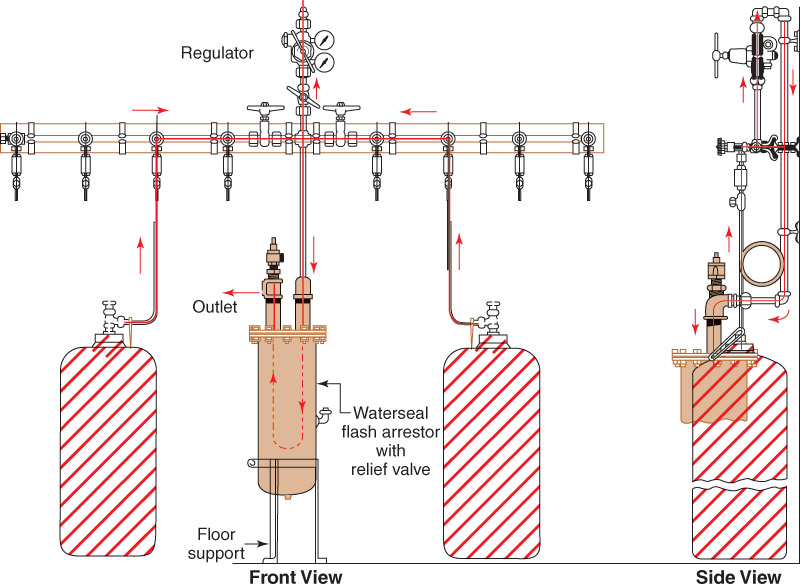
Because natural gas is delivered at a rather low pressure, injector-type torches are used both for cutting and for general heating. Some small torches have been developed that use compressed air and natural gas, particularly for soldering and brazing. Natural gas works well for many preheating operations. Natural gas systems should be protected by a waterseal or a blowback valve to keep air and oxygen from backfiring into the gas supply line. See Figure 11-17 for a waterseal flashback arrestor. Always consult all required safety authorities and regulations regarding natural gas systems before proceeding.
Liquefied petroleum gas is sold by the pound (or kilogram). Common sizes of tanks are: 4 1/4 lb (1.9kg), 11 lb (5kg), 20 lb (9.1kg), 30 lb (13.6kg), 40 lb (18.1kg), 60 lb (27.2kg), and 100 lb (45.4kg). LP gas can also be purchased by the gallon. Common sizes of storage tanks are: 120 gal (454L), 250 gal (946L), 500 gal (1893L), and 1000 gal (3785L).
A customer usually purchases the required tank size and returns it to the dealer for refilling. Larger sizes are usually leased. Industries that use large quantities of LP gas provide their own bulk storage. The fuel is delivered to them from bulk tank cars or trucks.
When LP gas is used as a fuel, the pressure must be regulated using an LP gas regulator. These regulators are most often supplied with two gauges. One gauge shows the pressure in the storage tank, and the other indicates the pressure in the torch or burner line. These regulators are usually attached to the tank using a standard POL commercial fitting.
Natural gas, available in tanks or cylinders, is also an excellent fuel gas for certain uses. It is particularly adaptable for cutting, soldering, brazing, and preheating. Regulators and proper fittings suitable for use with natural gas must be obtained.
Because natural gas is delivered at a rather low pressure, injector-type torches are used both for cutting and for general heating. Some small torches have been developed that use compressed air and natural gas, particularly for soldering and brazing. Natural gas works well for many preheating operations. Natural gas systems should be protected by a waterseal or a blowback valve to keep air and oxygen from backfiring into the gas supply line. See Figure 11-17 for a waterseal flashback arrestor. Always consult all required safety authorities and regulations regarding natural gas systems before proceeding.
11.11.2 Check Valves and Flashback Arrestors
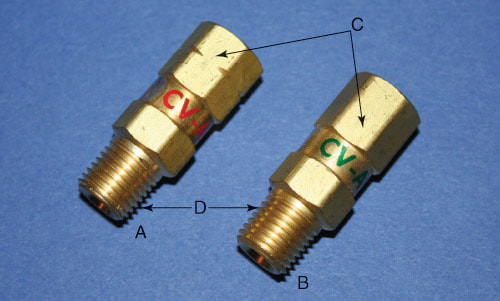
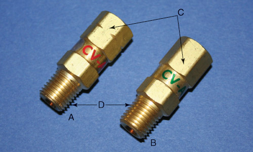
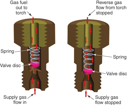
Check valves are used to prevent the reverse flow of gases through the torch, hoses, or regulators, see Figure 11-61. Figure 11-62 shows a check valve in the open and closed positions and explains how the check valve works.
A check valve allows a gas to flow in only one direction. Gas pressure opens the valve to allow gas flow. The valve closes when the gas stops flowing, or attempts to flow in the reverse direction. Check valves are generally installed at the torch inlet or placed at the regulator outlet. The valves may also be placed at both the torch and regulator.
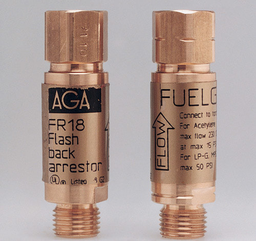
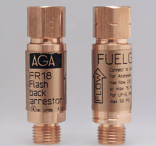
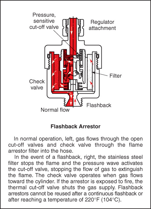
Flashback arrestors are designed to eliminate the possibility of an explosion in the regulator or cylinder. Figure 11-63 shows a flashback arrestor that has a built in check valve and a stainless steel flame arrestor to prevent flashbacks. The following safety valves are built into the flashback arrestor:
Figure 11-64 shows a flashback arrestor in the open and closed positions. An explanation of how the flashback arrestor works is also included. Another type of flashback arrestor is shown in Figure 11-65. This arrestor is also mounted on the regulator. It has the same four components as the flashback arrestor already mentioned.
A check valve allows a gas to flow in only one direction. Gas pressure opens the valve to allow gas flow. The valve closes when the gas stops flowing, or attempts to flow in the reverse direction. Check valves are generally installed at the torch inlet or placed at the regulator outlet. The valves may also be placed at both the torch and regulator.
Flashback arrestors are designed to eliminate the possibility of an explosion in the regulator or cylinder. Figure 11-63 shows a flashback arrestor that has a built in check valve and a stainless steel flame arrestor to prevent flashbacks. The following safety valves are built into the flashback arrestor:
- A reverse-flow check valve. This valve stops any flow of gas in the wrong direction.
- A pressure-sensitive cut-off valve that cuts off gas flow if an explosion occurs.
- A stainless steel filter that stops the flame.
- A heat-sensitive check valve that stops the gas flow if the arrestor reaches 220°F (104°C). A flashback arrestor is not reusable after reaching this temperature.
Figure 11-64 shows a flashback arrestor in the open and closed positions. An explanation of how the flashback arrestor works is also included. Another type of flashback arrestor is shown in Figure 11-65. This arrestor is also mounted on the regulator. It has the same four components as the flashback arrestor already mentioned.


